Diesel particulate filter overstress mitigation

a technology of particulate filter and overstress, which is applied in the direction of mechanical equipment, machines/engines, exhaust treatment, etc., can solve the problems of increasing non-uniformity, catastrophic, irreversible loss of filtration performance, and large internal stresses, so as to reduce stresses and prevent unacceptable fractures.

Inactive Publication Date: 2011-10-20
FORD GLOBAL TECH LLC
View PDF9 Cites 3 Cited by
  • Summary
  • Abstract
  • Description
  • Claims
  • Application Information

AI Technical Summary

Benefits of technology

[0002]Thus, to reduce the risk of sudden failure and to extend the working life of an economical monolithic DPF that is subjected to multiple regenerations, one would directionally seek to reduce the temperature non-uniformity in the DPF during regeneration. More particularly, one would reduce the non-uniformity in a way that lowers the stress in the ceramic to a level below some particular level that related to the strength of the ceramic and its coefficient of thermal expansion. In a research environment, this particular relationship can be developed by means of finite element analysis based on temperatures detected by a full field of tens of temperature sensors. To simplify the calculation, the filter ceramic body can be adequately approximated as a continuum material with a relatively simple type of non-isotropy, namely, one with physical properties generated from isotropic properties of the honeycomb wall materials in the particular geometry of the particular honeycomb. With such finite element calculations carried out at a series of time points during a regeneration, one may estimate the moment-by-moment internal stresses within the DPF and the corresponding probability of failure. This approach is suited for research.
[0003]However, the applicant herein recognizes that placing tens of sensors throughout a DPF is costly and will not be practical outside of a research and advanced development environment. Likewise, having a less appropriate estimator will either keep the in-use stresses lower than necessary or will lead to failures. If the stresses are kept too low, the operation leads to inefficiencies in the amount of fuel used to initiate more particulate filter regenerations than otherwise needed. If the less appropriate estimator errs on the other side, more failures will occur. Without having an appropriate simple estimator, the particulate filter might have to be designed for tolerance of fracture through the use of multi-segment mortared structures, but this approach increases manufacturing costs unnecessarily and serves as a concern for reduced emission reduction performance characteristics over time.
[0007]Therefore, it is preferred to have the highest gradients occur less generally within the length of DPF, namely, and preferably, mostly near the exit face and away from the center of the DPF during filter regeneration. In this way, the integral that is calculated is not as large as before, although the local radial gradient near the end face may be the same or higher than in the former case. This localization of the highest gradients may be achieved by design by controlling various engine operating parameters, such as with increased air flow, to move the highest temperatures and gradients to the rear of the DPF. By doing so, the integrated quantity, stress, as experienced by the DPF is lowered. However, the pair of temperature sensors that are both located near the end face is not able to sense the difference that has caused the high gradients to be concentrated near the exit face, therefore leading to a calculation of stresses that are likely to be higher than actual stresses, resulting in unnecessary inefficiency in fuel usage, in the effort to keep the DPF filter from being at risk of fracturing.
[0008]The systems and methods provided herein may help to correlate these stresses experienced by the DPF to those estimated with a small number of sensors, which include the two sensors near the exit face, for the radial temperature gradient measurement, as above, near the exit face together with an additional sensor to indicate how deeply into the filter the high temperature extends. In such way, it becomes possible to more closely correlate stresses to actual risk of DPF degradation, in turn, allowing better adjustments of the various DPF regeneration parameters and / or other engine operating parameters to reduce stresses experienced by the DPF during regeneration only as much as is necessary to prevent unacceptable risk of fracture.

Problems solved by technology

This non-uniformity is a growing concern because it has become especially large with the filters used with modern diesel engines with low engine-out levels of the nitrogen oxides.
Even with the choice of low coefficient of thermal expansion ceramics, such large temperature non-uniformity from an active regeneration can create internal stresses that are sufficiently large to fracture the filter ceramics.
In DPFs of the single-brick monolithic form that is preferred for large-volume manufacturing and economy, fracture across the monolith causes a sudden, catastrophic, and irreversible loss of filtration performance.
This uncertainty about maintenance of filtering function with monoliths has inhibited their wider use.
Indeed this risk for monoliths has led to wide commercial use of multi-segment mortared structures, in spite of the associated high material and manufacturing costs.
However, the applicant herein recognizes that placing tens of sensors throughout a DPF is costly and will not be practical outside of a research and advanced development environment.
Likewise, having a less appropriate estimator will either keep the in-use stresses lower than necessary or will lead to failures.
If the stresses are kept too low, the operation leads to inefficiencies in the amount of fuel used to initiate more particulate filter regenerations than otherwise needed.
If the less appropriate estimator errs on the other side, more failures will occur.
Without having an appropriate simple estimator, the particulate filter might have to be designed for tolerance of fracture through the use of multi-segment mortared structures, but this approach increases manufacturing costs unnecessarily and serves as a concern for reduced emission reduction performance characteristics over time.
As such finite element methods are cumbersome, simplified methods and systems for preventing the stress of a DPF are provided herein.
However, the pair of temperature sensors that are both located near the end face is not able to sense the difference that has caused the high gradients to be concentrated near the exit face, therefore leading to a calculation of stresses that are likely to be higher than actual stresses, resulting in unnecessary inefficiency in fuel usage, in the effort to keep the DPF filter from being at risk of fracturing.

Method used


Image

  • Diesel particulate filter overstress mitigation
  • Diesel particulate filter overstress mitigation
  • Diesel particulate filter overstress mitigation

Examples


Embodiment Construction

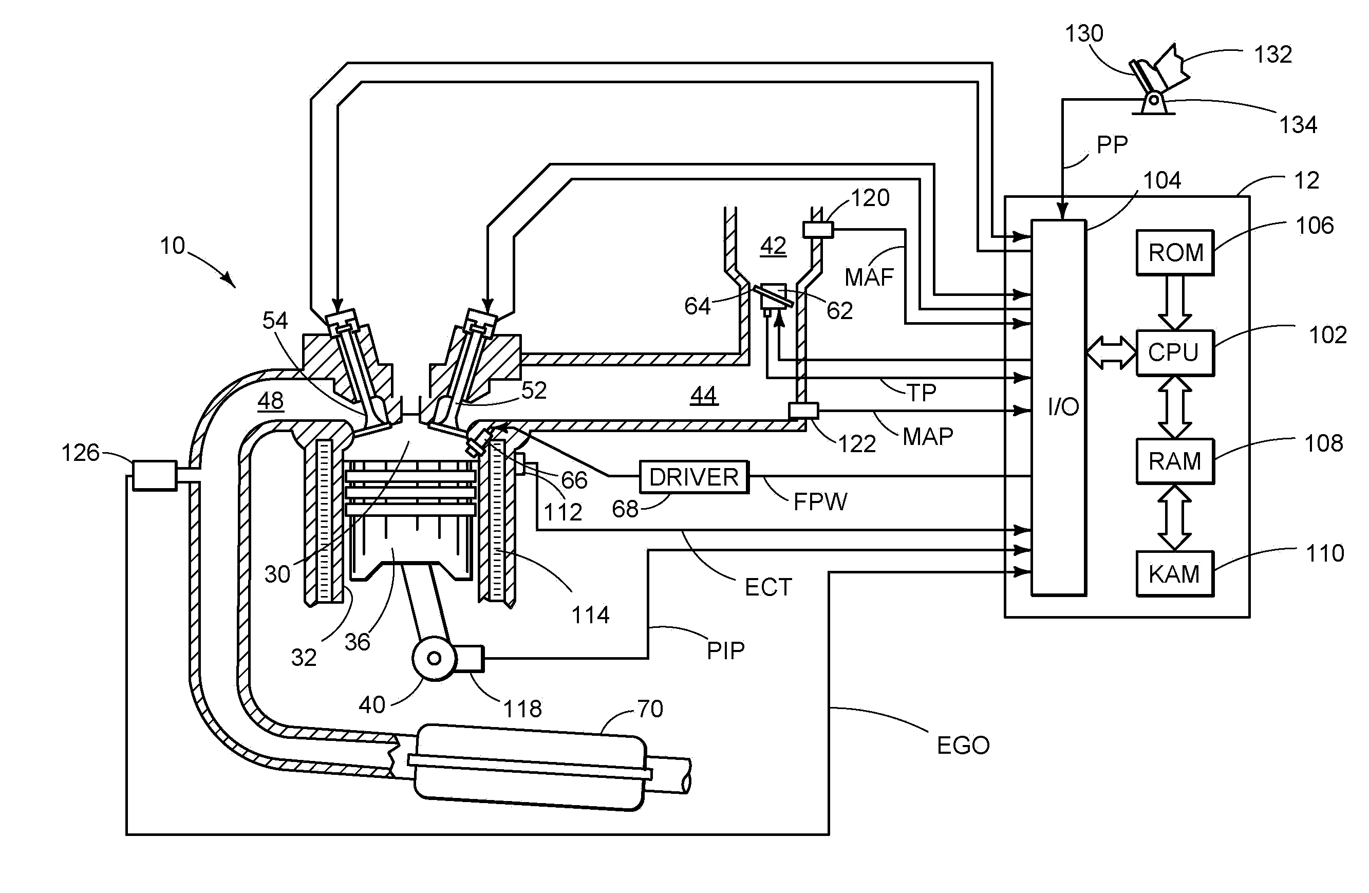
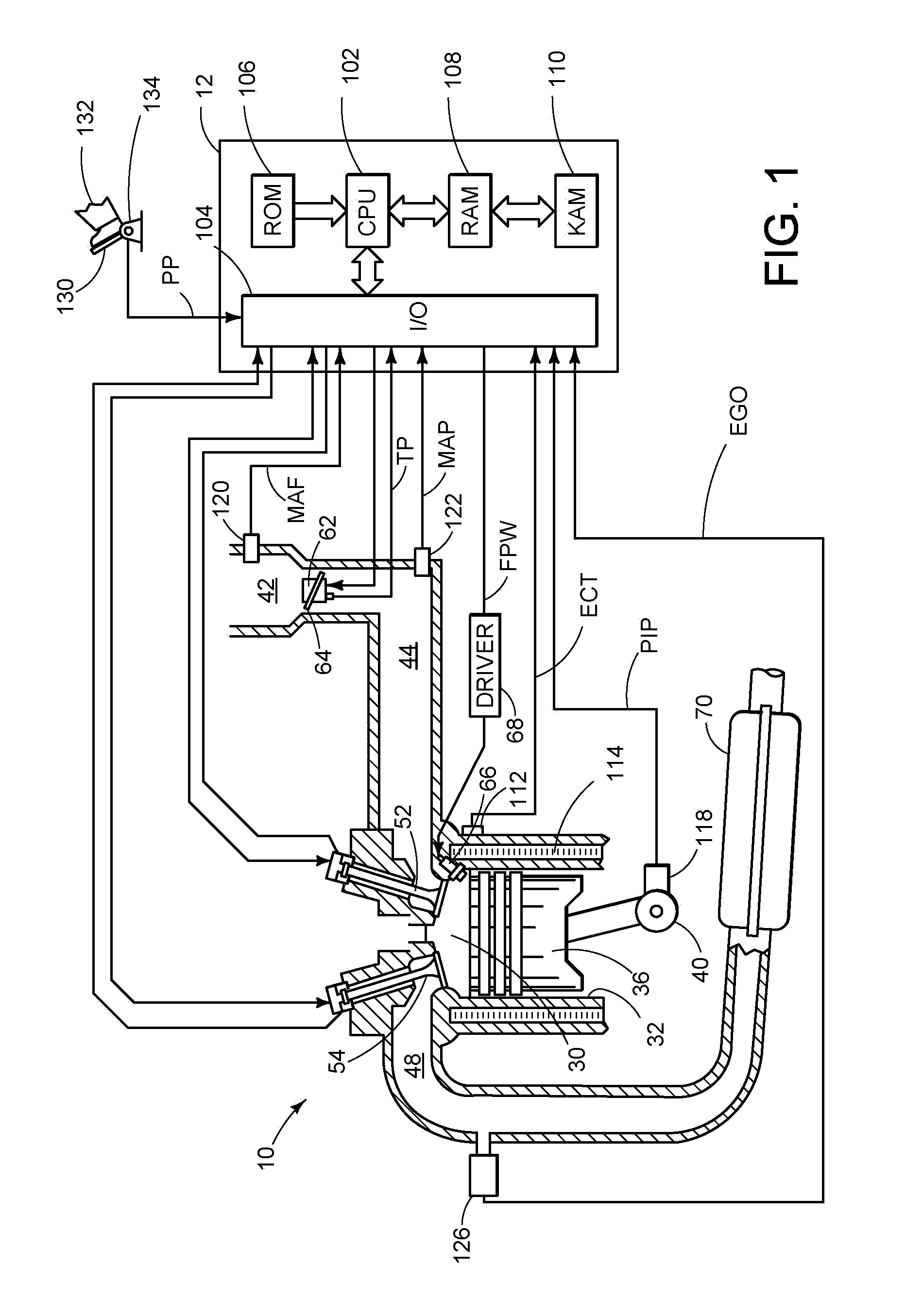
[0015]FIG. 1 is a schematic diagram showing one cylinder of multi-cylinder engine 10, which may be included in a propulsion system of an automobile. Engine 10 may include a diesel compression ignition engine. Engine 10 is controlled at least partially by a control system including controller 12 and by input from a vehicle operator 132 via an input device 130. In this example, input device 130 includes an accelerator pedal and a pedal position sensor 134 for generating a proportional pedal position signal PP. Combustion chamber (i.e. cylinder) 30 of engine 10 includes combustion chamber walls 32 with piston 36 positioned therein. Piston 36 is coupled to crankshaft 40 so that reciprocating motion of the piston is translated into rotational motion of the crankshaft. Crankshaft 40 may be coupled to at least one drive wheel of a vehicle via an intermediate transmission system. Further, a starter motor may be coupled to crankshaft 40 via a flywheel to enable a starting operation of engine...


PUM


Abstract

Methods and systems for reducing overstress of a DPF are provided herein. One example of such a method is based on a radial temperature gradient near the exit face of the diesel particulate filter. In this way, it becomes possible to more closely correlate radial stresses to actual risk of DPF fracture.

Description

BACKGROUND AND SUMMARY[0001]Temperature non-uniformity within a diesel particulate filter (DPF) occurs during filter regeneration. This non-uniformity is a growing concern because it has become especially large with the filters used with modern diesel engines with low engine-out levels of the nitrogen oxides. In the past, those nitrogen oxide gases have served to passively oxidize carbon soot and thereby remove the accumulated soot. With the modern engines, the diesel soot accumulates in the filter until an active step is taken to initiate soot combustion, beginning an active regeneration, to burn off most of the soot within a relatively short time interval, and creating more severe temperature non-uniformity. Even with the choice of low coefficient of thermal expansion ceramics, such large temperature non-uniformity from an active regeneration can create internal stresses that are sufficiently large to fracture the filter ceramics. In DPFs of the single-brick monolithic form that i...

Claims


Application Information

Patent Timeline
Patent Type & Authority Applications(United States)
IPC IPC(8): F01N11/00F01N3/023
CPCF01N11/002F01N2560/06Y02T10/47F01N2900/1602F01N2560/14Y02T10/40
Inventor CROSBIE, GARY M.
Owner FORD GLOBAL TECH LLC
Why Eureka
Try Eureka