Tug Boat Engine Emissions Control Suite

a technology for engine emissions and control suites, which is applied in the direction of electric control, machines/engines, fuel injecting pumps, etc., can solve the problems of increasing nox emissions, increasing increasing emissions of carbon monoxide (co), and hydrocarbons (hc) in the exhaust, etc., so as to reduce peak temperatures, reduce nitrogen oxide production, and increase emissions of particulate matter

Inactive Publication Date: 2011-10-20
HELM ENVIRONMENTAL SOLUTIONS
View PDF8 Cites 9 Cited by
  • Summary
  • Abstract
  • Description
  • Claims
  • Application Information

AI Technical Summary

Benefits of technology

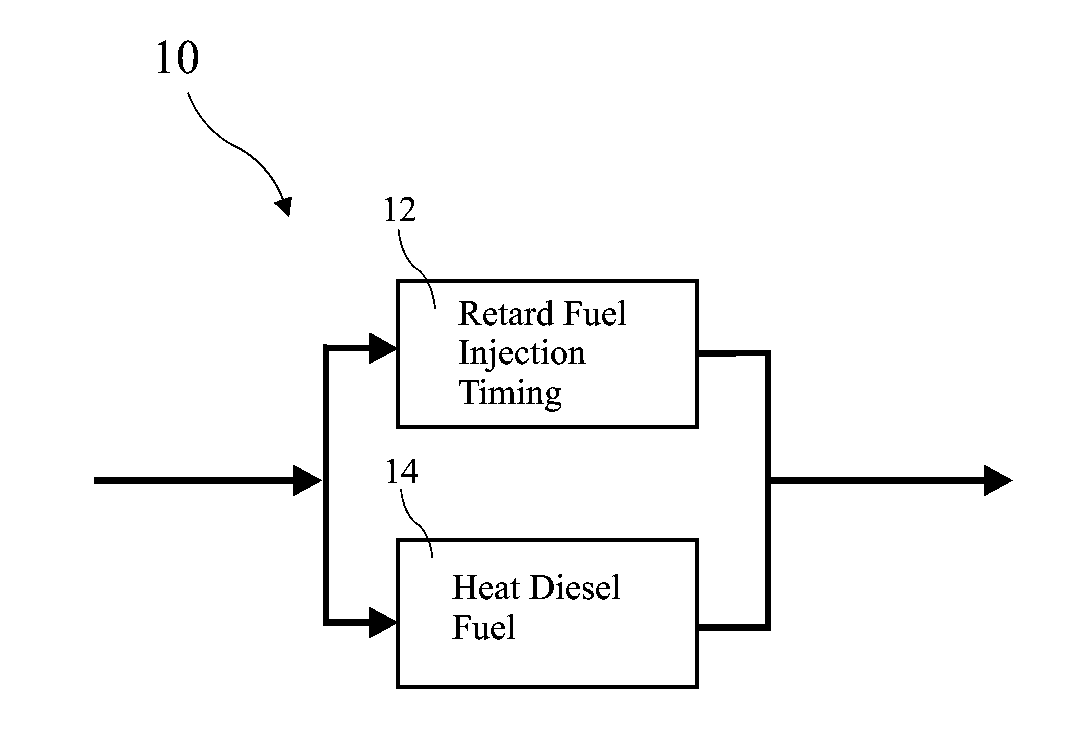
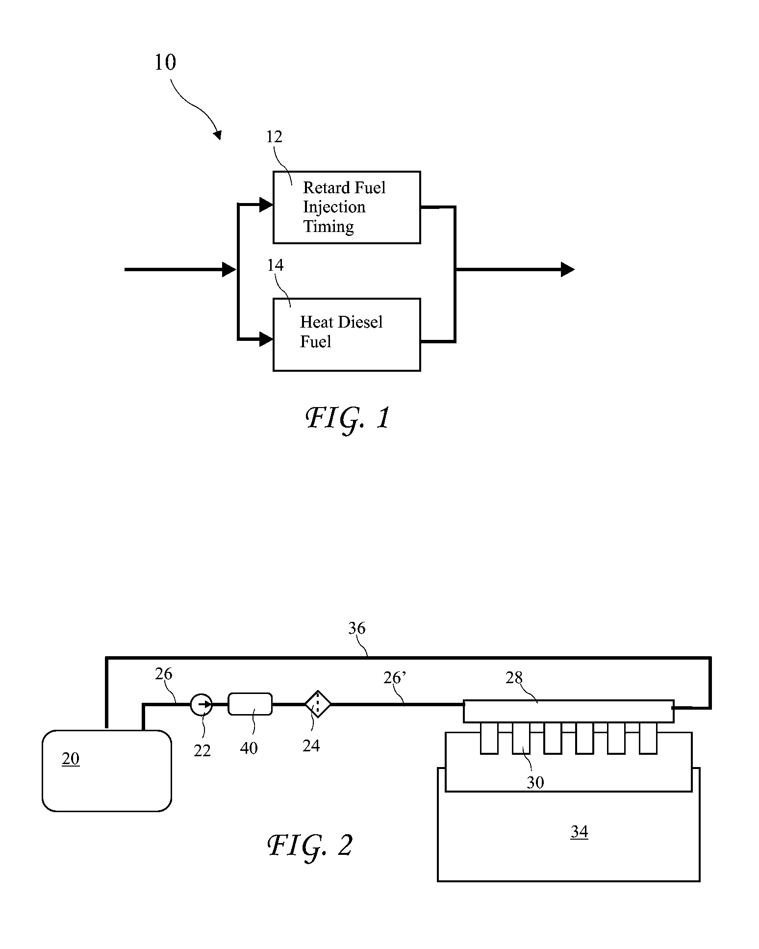
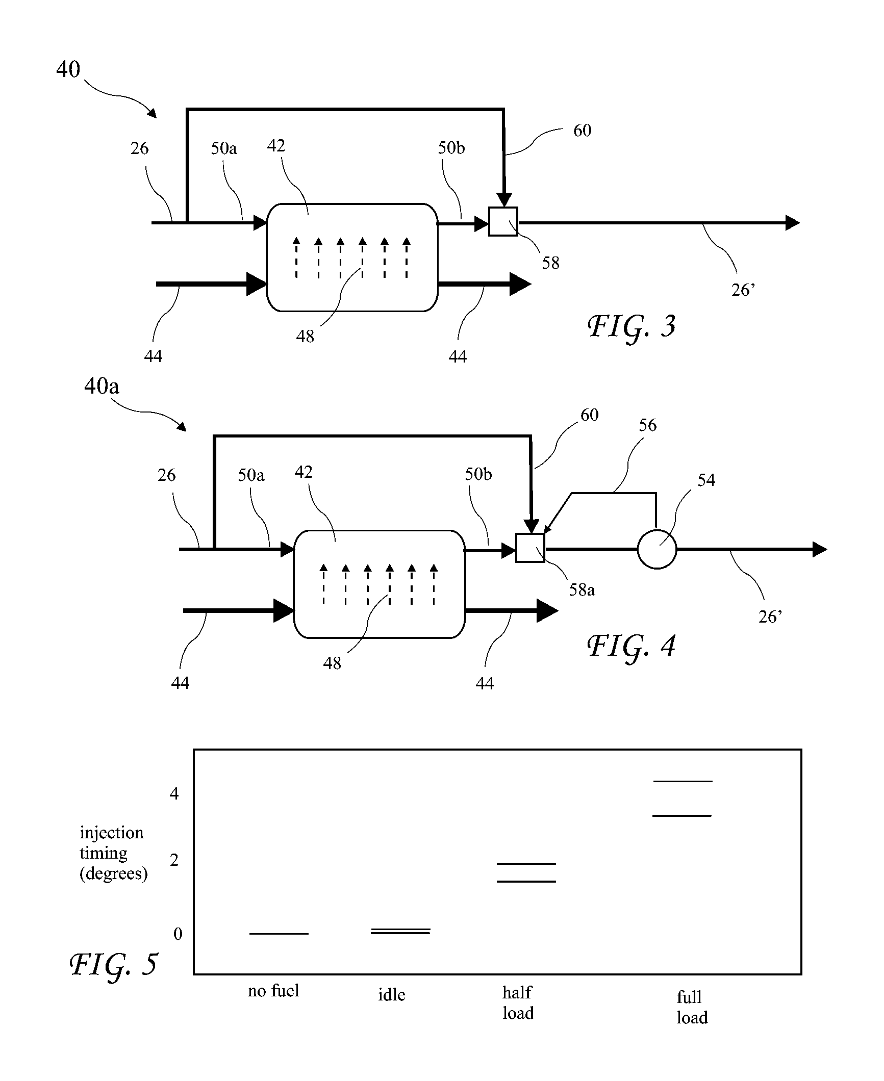
[0011]Various aspects of the present invention address the above and other needs by providing a tug boat diesel engine emissions control suite including modified fuel injectors with a built in injection timing retard feature and diesel fuel heating. Tug boats are now required to comply with USEPA emission standards under 40 CFR Part 94 regulations. Retarding the fuel injection timing reduces peak temperatures during combustion which in turn reduces production of Nitrogen Oxides (NOx) but also increases emissions of particulate matter (PM), Carbon Monoxide (CO), and Hydrocarbons (HC) in the exhaust. Heating the diesel fuel provides a reduction in PM, CO, and HC to acceptable levels. Experiments showed that a novel modification to a plunger in the fuel injectors providing up to six degrees of fuel injection timing retarding, and fuel heated to 120 to 140 degrees Fahrenheit, resulted in meeting the 40 CFR Part 94 regulations.

Problems solved by technology

Retarding the fuel injection timing reduces peak temperatures during combustion which in turn reduces production of Nitrogen Oxides (NOx) but also increases emissions of particulate matter (PM), Carbon Monoxide (CO), and Hydrocarbons (HC) in the exhaust.
Retarding the fuel injection timing reduces NOx but unfortunately increases emissions of Particulate Matter (PM), Carbon Monoxide (CO), and Hydrocarbons (HC) in the exhaust.
The higher compression ratio significantly reduces emissions of Particulate Matter (PM) but results in some increase in NOx emissions.

Method used


Image

  • Tug Boat Engine Emissions Control Suite
  • Tug Boat Engine Emissions Control Suite
  • Tug Boat Engine Emissions Control Suite

Examples


Embodiment Construction

[0029]The following description is of an embodiment presently contemplated for carrying out the invention. This description is not to be taken in a limiting sense, but is made merely for the purpose of describing one or more preferred embodiments of the invention, and other embodiments derived by those skilled in the art are intended to come within the scope of the present invention. The scope of the invention should be determined with reference to the claims.

[0030]Reduction of engine emissions have proven to be very difficult due to the complex nature of combustion in engines. Methods have generally consisted of trial and error and lack accurate models capable of predicting results. Further, emissions reduction is generally a non-linear multi-dimensional problem including the interaction of fuel control, air intake control, engine bore and stroke, combustion chamber design, operating temperatures, and other design and operation parameters. The overall environment of engine emission...


PUM


Abstract

A tug boat diesel engine emissions control suite includes modified fuel injectors including a fuel injection timing retard feature, and diesel fuel heating. Tug boats are now required to comply with USEPA emission standards under 40 CFR Part 94 regulations. Retarding the fuel injection timing reduces peak temperatures during combustion which in turn reduces production of Nitrogen Oxides (NOx) but also increases emissions of particulate matter (PM), Carbon Monoxide (CO), and Hydrocarbons (HC) in the exhaust. Heating the diesel fuel provides a reduction in increased PM, CO, and HC to acceptable levels. Experiments showed that a novel modification to a plunger in the fuel injectors providing up to six degrees of fuel injection timing retarding, and fuel heated to 120 to 140 degrees Fahrenheit, resulted in meeting the 40 CFR Part 94 regulations.

Description

[0001]The present application is a Continuation In Part of U.S. patent application Ser. No. 12 / 759,890 filed Apr. 14, 2010, which application is incorporated in its entirety herein by reference.BACKGROUND OF THE INVENTION[0002]The present invention relates to the control of tug boat engines and in particular to reducing emission levels of tug boat engines to comply with USEPA emission standards under 40 CFR Part 94 regulations which became effective in January 2004.[0003]USEPA emission standards under 40 CFR Part 94 became effective in January 2007 for category 2, engine displacement between five and fifteen liters cylinder. The standards include:[0004]Nitrogen oxides (Nox)+Total Hydrocarbon: (THC)=7.8 grams / kw-hr[0005]Carbon Monoxide (CO)=5 gms / kw-hr; and[0006]Particulate matter (PM)=0.27 gms / kw-hr.[0007]The above standards are also known as Tier 2 standards.[0008]Tug boats commonly use an Electro Motive Division (EMD) 645 series engine. The 645 series engines are a family of eight...

Claims


Application Information

Patent Timeline
Patent Type & Authority Applications(United States)
IPC IPC(8): F02D7/00
CPCF02D41/401F02D2250/36F02D2250/38Y02T10/44F02M57/023F02M59/26F02M59/265F02M53/02Y02T10/40
Inventor TALWAR, MAHESHBERNARD, FRANCOIS
Owner HELM ENVIRONMENTAL SOLUTIONS
Why Eureka
Try Eureka