Device, Method and Use for Transfer of Equipment for a Wireline Operation in a Well
- Summary
- Abstract
- Description
- Claims
- Application Information
AI Technical Summary
Benefits of technology
Problems solved by technology
Method used
Image

Examples
first embodiment
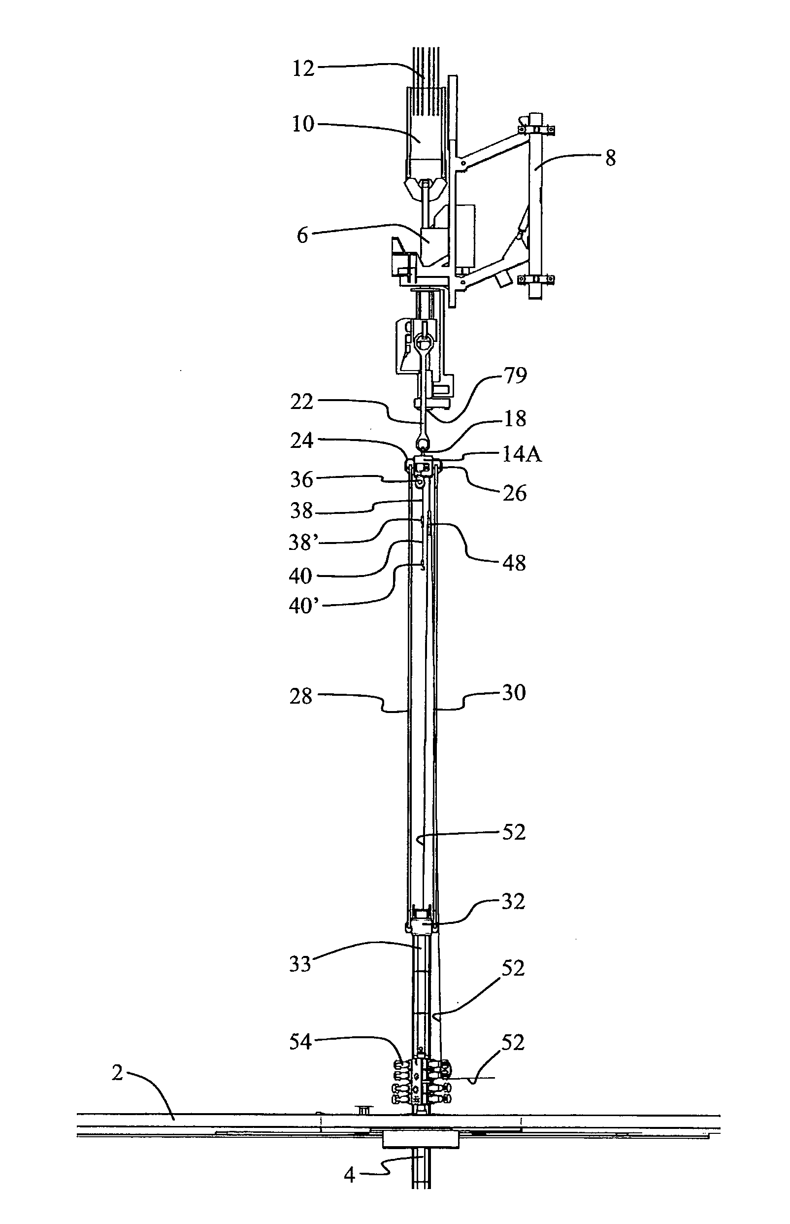
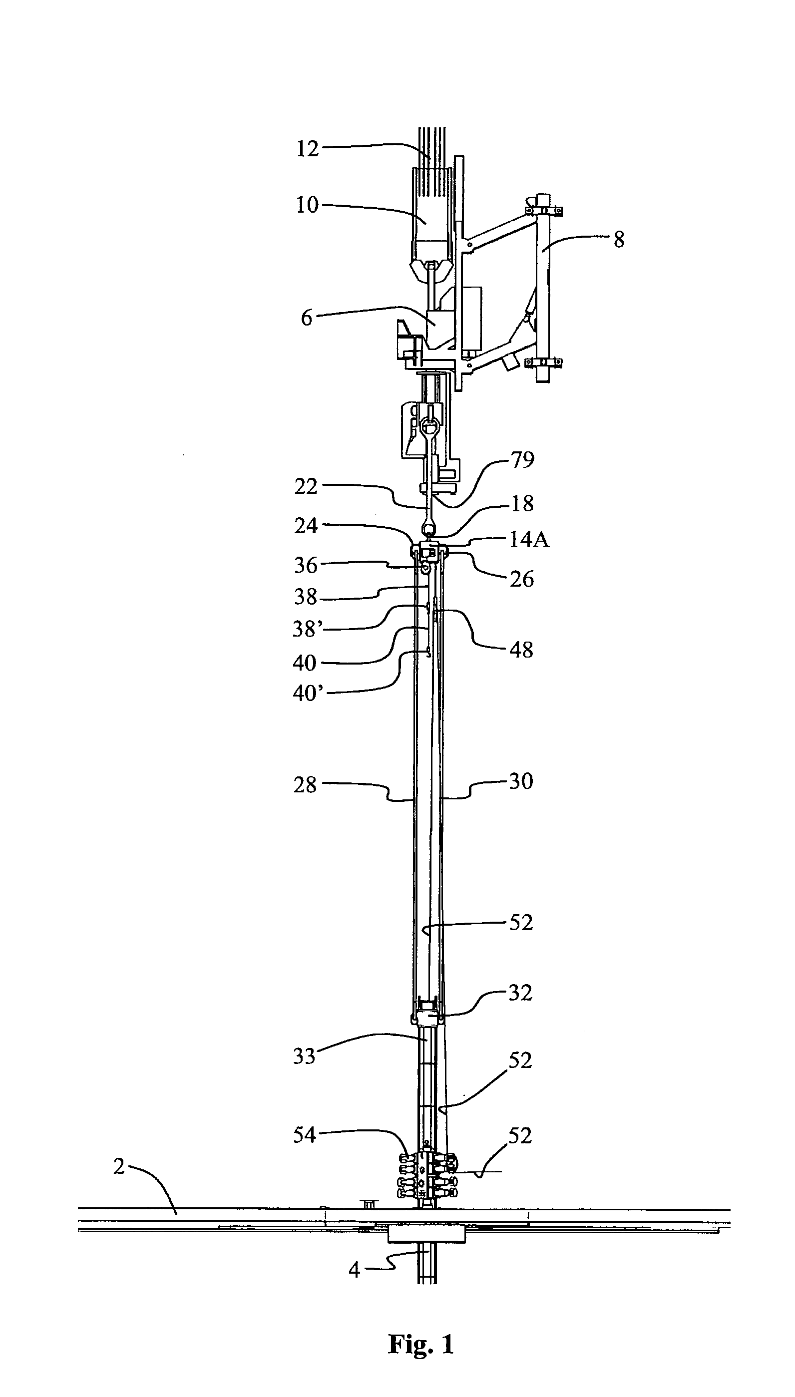
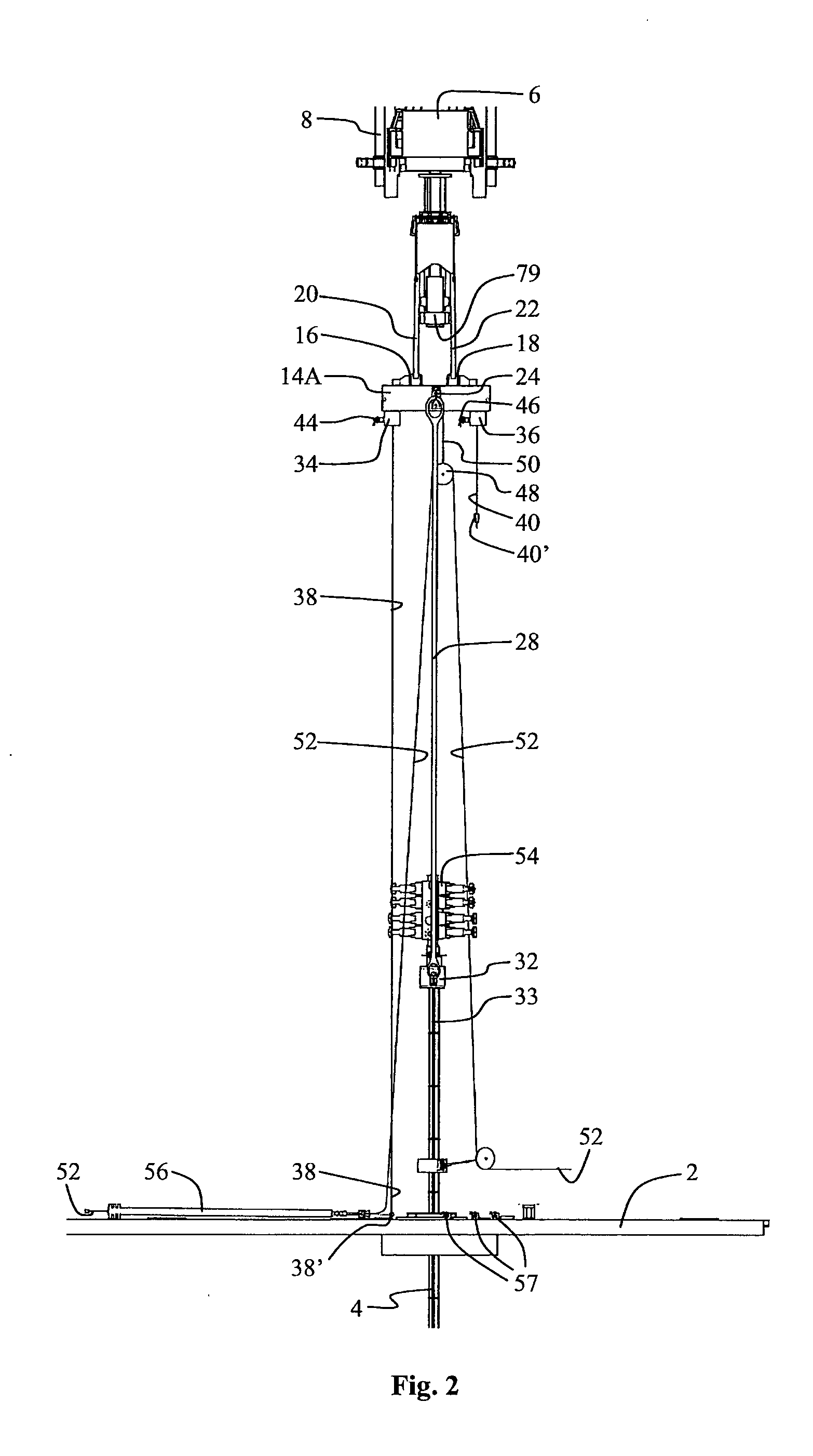
[0105]The figures also show a beam 14A according to the invention disposed in a releasable manner, and in its position of use, between the top drive 6 and the drill floor 2. At its upper side, the beam 14A is provided with two first lifting lugs 16, 18, each of which is releasably connected to a lifting bail 20, 22. These lifting bails 20, 22 extend in a parallel manner up to the top drive 6 and are releasably connected to lifting lugs thereon. Midway on each of its longitudinal sides, the beam 14A is also provided with a second lifting lug 24, 26, which is releasably connected to a respective lifting bail 28, 30. These bails 28, 30 extend in a parallel manner down towards the drill floor 2 and are releasably connected to a connection sleeve 32 attached around an upper end 33 of the riser 4. In this manner, the beam 14A is structured for releasable connection to and between the top drive 6 and the lifting bails 28, 30. By so doing, the beam 14A is also structured in a manner allowin...
second embodiment
[0110]Referring to FIGS. 6-10, a beam 14B according to the invention will now be shown.
[0111]Also in this second embodiment, the beam 14B is provided with two separate, remote-controlled, hydraulic winches 34, 36, each having a respective lifting wire 38, 40 and a respective lifting hook 38′, 40′. Each lifting wire 38, 40 emerges from its winch 34, 36 via a support point which, in this embodiment, assumes the form of a respective wire pulley 58, 60, which forms a part or a portion of each winch 34, 36. Such a wire pulley 58, 60, however, is not a prerequisite. In other embodiments, the lifting wire 38, 40 may emerge directly from the wire drum of the winch 34, 36, whereby the wire drum forms said support point for the lifting wire 38, 40.
[0112]Each winch 34, 36 is structured so as to be movable along a respective longitudinal half of the beam 14B for individual, remote-controlled transfer along a joint path of motion in the longitudinal direction of the beam. Each winch 34, 36 may t...
third embodiment
[0115]Referring to FIGS. 11-15, a beam 14C according to the invention will now be shown. The figures are of principal nature and show only the most essential elements of the embodiment.
[0116]In this third embodiment, the beam 14C is provided with one remote-controlled, hydraulic winch 34 fixed at one end of the beam 14C. A lifting wire 38 emerges from the winch 34 and is first carried around half the circumference of a non-movable disc wheel 80 which, via a mounting bracket 82, is fixed at the opposite side of the beam 14C. The lifting wire 38 then extends in the direction of the winch 34 and around half the circumference of a movable hook-height adjustment disc wheel 84 and further around a quarter of the circumference of a movable support disc wheel 86 disposed closer to the non-movable disc wheel 80. By so doing, the lifting wire 38 will extend vertically from the support disc wheel 86 when the beam 14 is in its position of use. Thus, the support disc wheel 86 forms a movable sup...
PUM
 Abstract
Description
Claims
Application Information
 - R&D
- Intellectual Property
- Life Sciences
- Materials
- Tech Scout
- Unparalleled Data Quality
- Higher Quality Content
- 60% Fewer Hallucinations
Browse by: Latest US Patents, China's latest patents, Technical Efficacy Thesaurus, Application Domain, Technology Topic, Popular Technical Reports.
© 2025 PatSnap. All rights reserved.Legal|Privacy policy|Modern Slavery Act Transparency Statement|Sitemap|About US| Contact US: help@patsnap.com