Bumper beam with integrated energy absorber

a technology of energy absorber and bumper beam, which is applied in the direction of domestic articles, lamination, applications, etc., can solve the problems of cost of manufacture, and achieve the effect of improving manufacturing costs and simplifying the manufacturing process

Active Publication Date: 2011-10-20
MAGNA INTERNATIONAL INC
View PDF4 Cites 10 Cited by
  • Summary
  • Abstract
  • Description
  • Claims
  • Application Information

AI Technical Summary

Benefits of technology

[0006]Also included is a beam cover plate connected to the beam structural member through the use of resistive implant welding, which simplifies the manufacturing process, and improves manufacturing costs. There are two vehicle attachment plates which are overmolded to the beam cover plate, the vehicle attachment plates allow for the beam cover plate to be attached to a vehicle.

Problems solved by technology

However, components used for absorbing energy during a collision of most current designs are made of metal, which is costly to manufacture.

Method used


Image

  • Bumper beam with integrated energy absorber
  • Bumper beam with integrated energy absorber
  • Bumper beam with integrated energy absorber

Examples


Embodiment Construction

[0020]The following description of the preferred embodiment(s) is merely exemplary in nature and is in no way intended to limit the invention, its application, or uses.

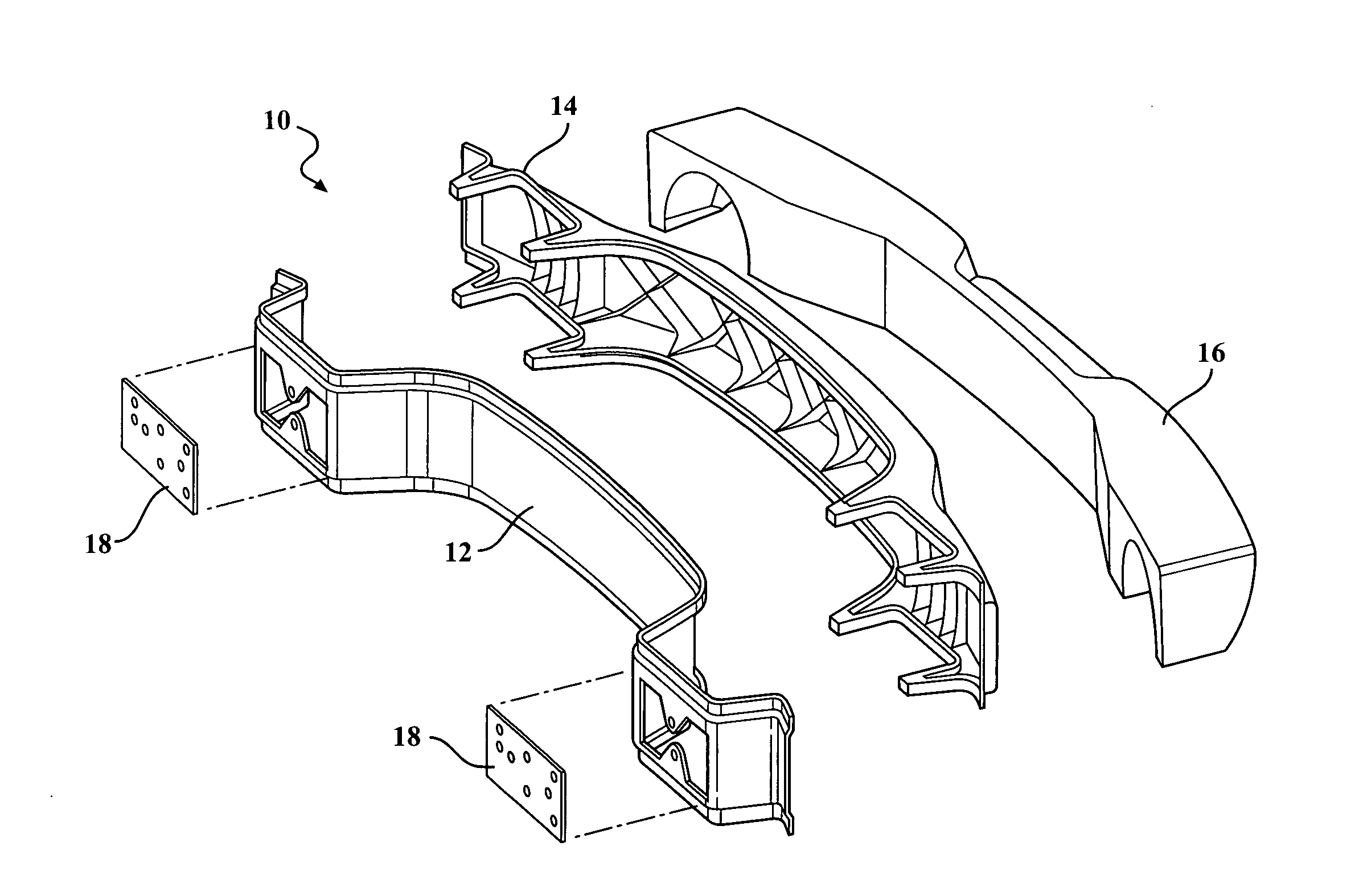
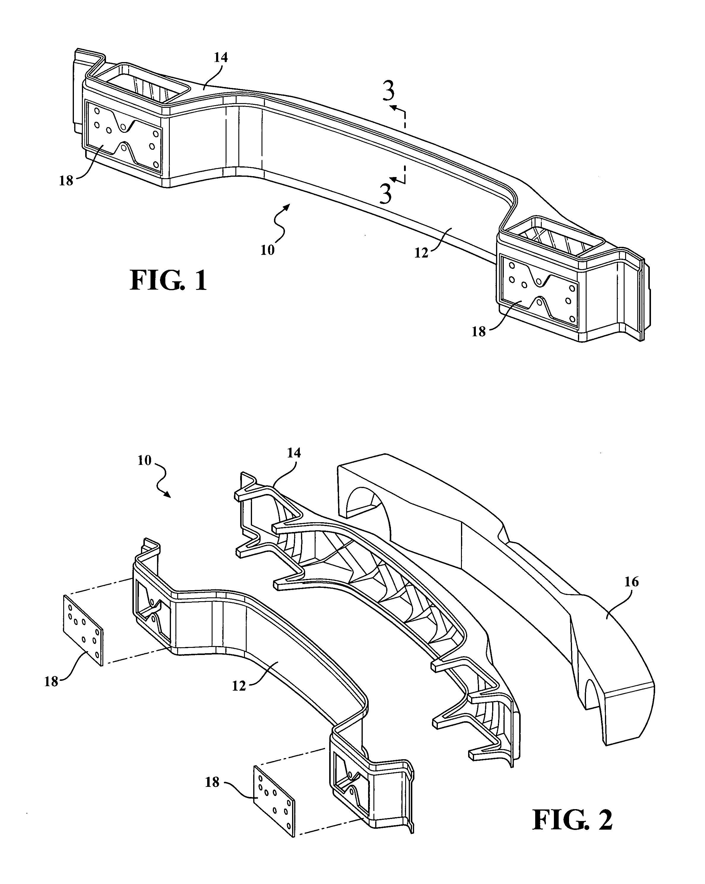
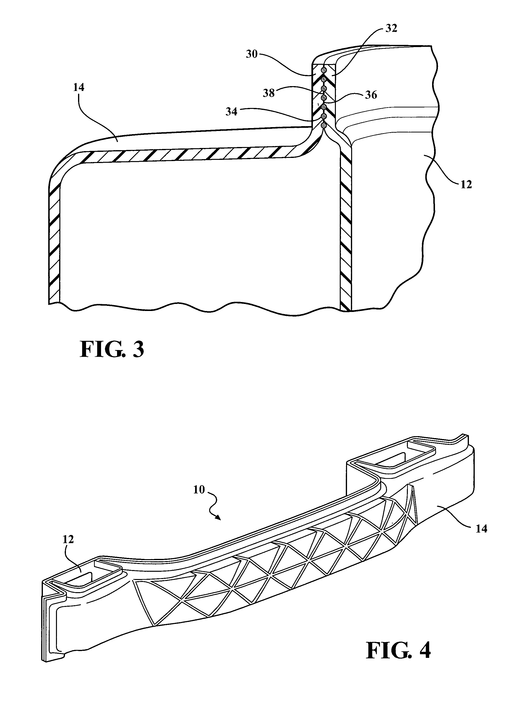
[0021]A bumper beam having an integrated energy absorber is shown in the Figures generally at 10. The bumper beam 10 includes a beam cover plate 12, a beam structural member 14, and a foam energy absorber 16. The cover plate 12, beam structural member 14, and foam energy absorber 16 are all connected together, with the beam structural member 14 located between the cover plate 12 and the foam energy absorber 16.

[0022]Both the cover plate 12 and the beam structural member 14 are made of molded long glass fiber (LGF) nylon; they are connected by resistance implant welding (RIW). The foam energy absorber 16 is made from expanded polypropylene (EPP) material using a steam injection molding process, and is fastened to the beam structural member 14.

[0023]Also included is a plurality of vehicle attachment plates 18. In this e...


PUM

PropertyMeasurementUnit
thicknessaaaaaaaaaa
energyaaaaaaaaaa
energy absorbingaaaaaaaaaa

Abstract

The present invention is directed to an energy absorbing component externally mounted to a vehicle having a beam structural member and at least one energy absorber operably connected to the beam structural member. The energy absorber absorbs energy when the vehicle undergoes a collision. Also included is a beam cover plate connected to the beam structural member through the use of resistive implant welding, which simplifies the manufacturing process, and improves manufacturing costs. There are two vehicle attachment plates which are overmolded to the beam cover plate, the vehicle attachment plates allow for the beam cover plate to be attached to a vehicle. The beam cover plate, beam structural member, and energy absorber form a component that is operable to function as a bumper that is connected to a vehicle, which absorbs energy during a collision.

Description

CROSS-REFERENCE TO RELATED APPLICATIONS[0001]This application claims priority to U.S. Provisional Application No. 61 / 342,159 filed on Apr. 9, 2010. The disclosure of the above application is incorporated herein by reference.FIELD OF THE INVENTION[0002]The present invention relates to an energy absorbing component for a bumper or fascia made of a composite material.BACKGROUND OF THE INVENTION[0003]Most motor vehicles in use today have some type of bumper or fascia mounted to the front end and rear end of the vehicle. Current designs for most bumpers have some sort of device or component which is used for absorbing energy during a collision. This reduces the amount of energy transferred to the occupants of the vehicle.[0004]However, components used for absorbing energy during a collision of most current designs are made of metal, which is costly to manufacture. Accordingly, there exists a need for a bumper which includes a component able to absorb energy during a vehicle collision, wi...

Claims


Application Information

Patent Timeline
Patent Type & Authority Applications(United States)
IPC IPC(8): B60R19/26B32B37/04
CPCB29C65/342B29C66/545B29C66/1312B29C66/71B29C66/7212B29C66/72141B29L2031/3044B60R19/03B60R19/22B60R2019/184B60R2019/1866B60R2019/1886B29C65/344B29C66/543B29C65/3476B29K2077/00B29K2309/08B29C66/73921B29K2023/12
Inventor CAVE, ALAN C.DERNOVSEK, ROBERTHAVEMAN, RICHARD W.
Owner MAGNA INTERNATIONAL INC
Why Eureka
Try Eureka