Spark plug

Active Publication Date: 2011-10-20
NGK SPARK PLUG CO LTD
View PDF8 Cites 6 Cited by
  • Summary
  • Abstract
  • Description
  • Claims
  • Application Information

AI Technical Summary

Benefits of technology

[0012]Aspect 3. In accordance with another aspect of the present invention, there is provided a spark plug as described above, wherein the butt portion butts against the support ledge via an annular packing for maintaining gas tightness.
[0032]In association with a demand for a reduction of the size (diameter) of the spark plug, there is demand for a reduction of the diameter of the metallic shell, such as a reduction of the thread diameter of the mounting screw formed on the outer circumferential surface of the metallic shell to M12. Under such circumstances, difficulty is encountered in securing the thickness of the insulation member. In such circumstances, when the support ledge is provided in a region located frontward of the filler, the insulation space between the support ledge and the insulation member reduces in size, or the wall thickness of the insulation member reduces. As a result, an abnormal discharge is generated between the support ledge and the insulation member, or voltage endurance is impaired, with a resultant occurrence of damage to the insulation member, such as formation of a hole in the insulation member. By contrast, according to the invention described in Aspect 10, the inner circumferential surface of the mating hole portion is formed such that the diameter thereof is not reduced toward the front end of the metallic shell. As a result, the insulation member can have an increased thickness, whereby voltage endurance can be enhanced. Such an effect is more marked with a small-sized spark plug having a thread diameter of the mounting screw formed on the outer circumferential surface of the metallic shell of M12 (metric threads having a major diameter of 12 mm) or less as in the case of the invention described in Aspect 12.

Problems solved by technology

Continuation of such a condition leads to impairment in gas tightness.
Also, impairment in gas tightness and the formation of the clearance results in impairment in heat transference for transferring heat of a front end portion of the insulation member 1 to the engine head.
However, the formation of a clearance in the gas tightness-maintaining portion causes impairment in heat transference.
As a result, a front end region of the insulation member 1 and the center electrode 5 assume excessively high temperature, potentially resulting in occurrence of preignition or thermal erosion of the electrode.

Method used


Image

  • Spark plug
  • Spark plug
  • Spark plug

Examples


Embodiment Construction

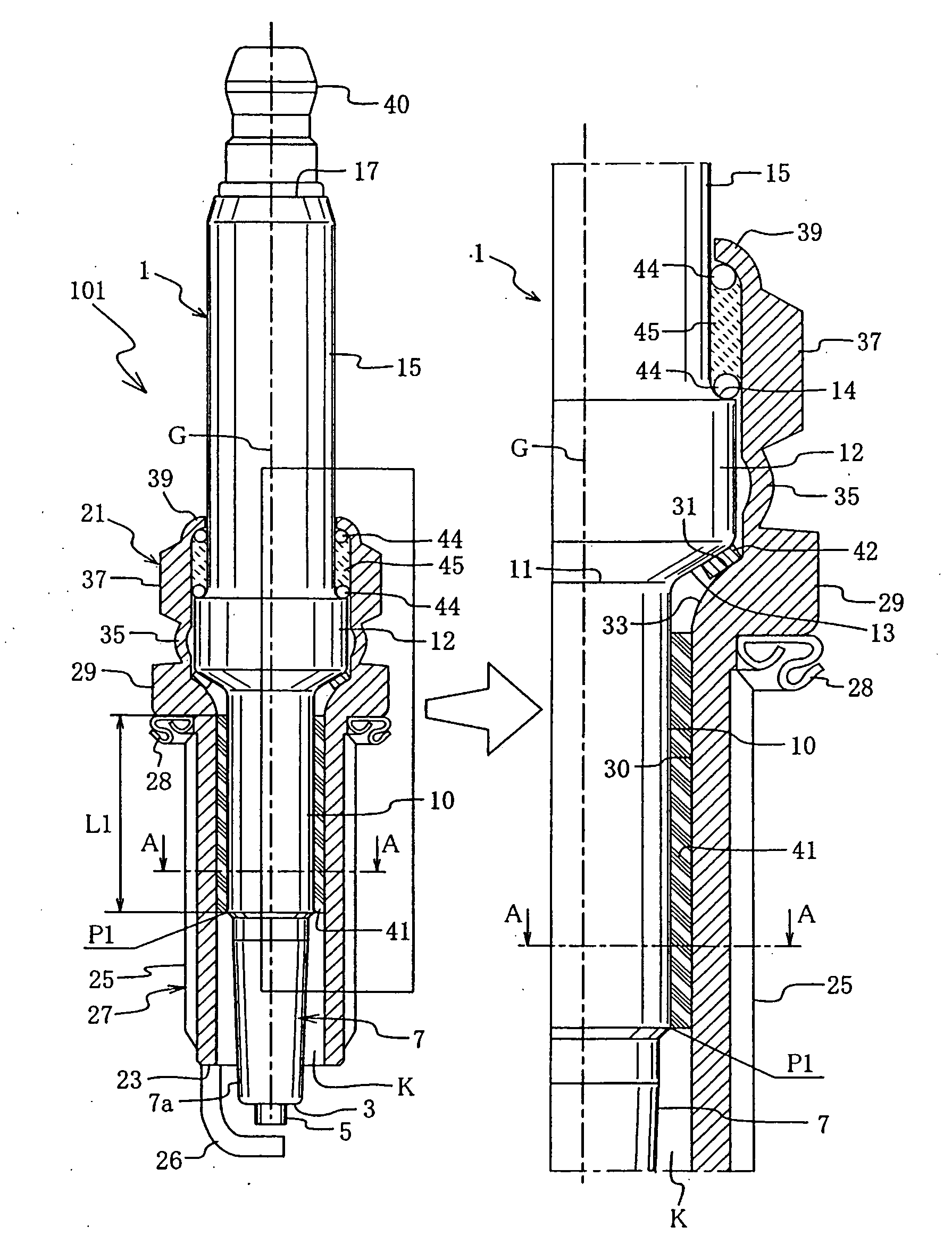
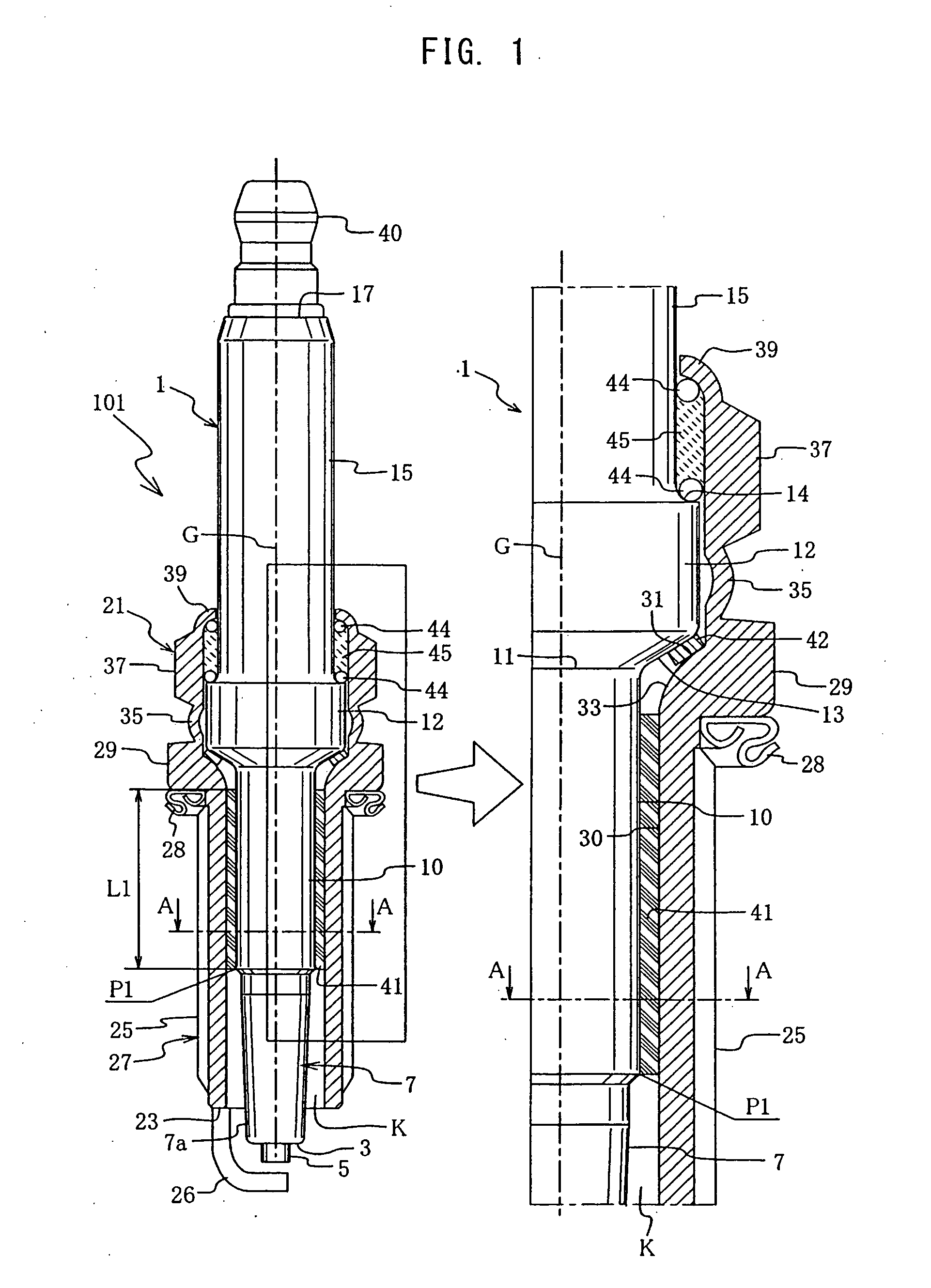
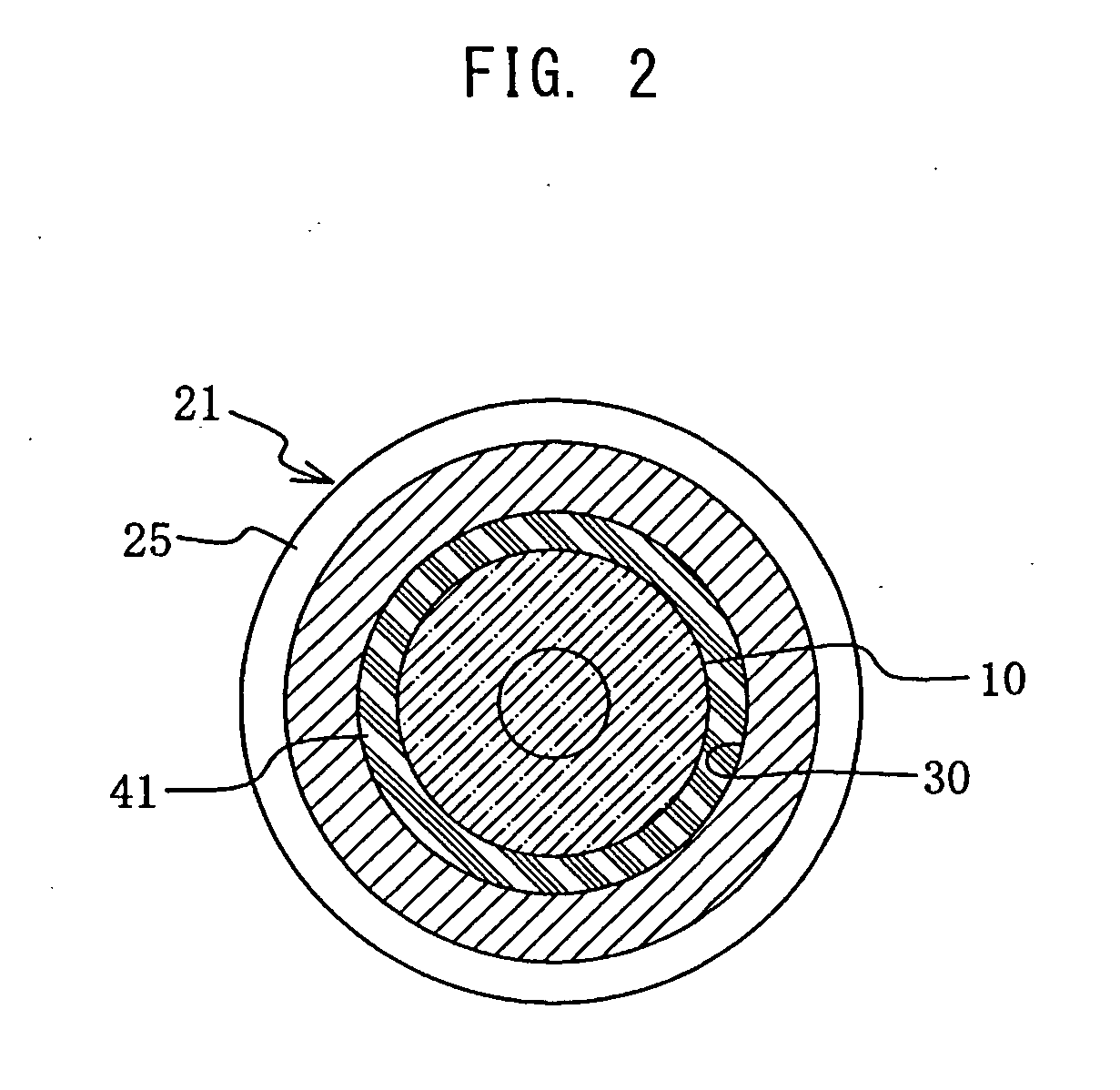
[0044]A spark plug according to an embodiment of the present invention will be described in detail with reference to FIGS. 1 and 2. FIG. 1 is an explanatory, vertical sectional view of the spark plug and an enlarged view showing essential portions of the spark plug. A spark plug 101 includes a hollow, shaft-like (tubular) insulation member 1 made of ceramic and having a center electrode 5 projecting from a front end 3 thereof, and a tubular metallic shell 21 fixing the insulation member 1 in a surrounding manner and having a ground electrode 26 provided at a front end 23 thereof. In the present embodiment, the metallic shell 21 is made of low-carbon steel (specifically, carbon steel for cold heading having a carbon content of 0.25%).

[0045]The metallic shell 21 includes a cylindrical, straight tube portion 27 located toward the front end of the metallic shell 21. A mounting screw (e.g., M12 or M14) 25, is formed on the outer circumferential surface of the straight tube portion 27, an...


PUM


Abstract

[Objective] To provide a spark plug which is configured such that an insulation member, from which a center electrode projects, is pressed frontward and held in a metallic shell, and is fixed by means of crimping the rear end of the metallic shell, and which can prevent a drop in gas tightness between the metallic shell and the insulation member due to a difference in thermal expansion therebetween.[Means for Solution] In a spark plug in which a mating shaft portion (10) of an insulation member (1) is loose-fitted into a mating hole portion (30) of a metallic shell (21), a filler (41) for maintaining gas tightness is charged between the outer circumferential surface of the mating shaft portion (10) and the inner circumferential surface of the mating hole portion (30). Despite the thermal expansion difference, the gas tightness is maintained, because the filler (41) for maintaining gas tightness is charged between the inner and outer circumferential surfaces.

Description

FIELD OF THE INVENTION[0001]The present invention relates to a spark plug (ignition plug) for an internal combustion engine.BACKGROUND OF THE INVENTION[0002]A known spark plug for providing ignition in an internal combustion engine, such as an automobile engine, has, for example, a structure shown in FIG. 10 (refer to, for example, Japanese Patent Application Laid-Open (kokai) No. 2005-129398). This spark plug 201 includes an insulation member (ceramic insulator) 1 made of ceramic, assuming the form of a hollow, tubular shaft, and having a center electrode 5 projecting from the front end (lower end in FIG. 10) thereof, and a tubular metallic shell 21, which fixedly holds the insulation member 1 in a surrounding manner. The metallic shell 21 is formed such that the inner circumferential surface is greater in diameter (inside diameter) at a rear portion than at a front portion. The metallic shell 21 has an annular support ledge 24 on the inner circumferential surface of its portion lo...

Claims


Application Information

Patent Timeline
IPC IPC(8): H01T13/04
CPCH01T13/36H01T13/16
Inventor KYUNO, JIROSUZUKI, AKIRAMUSASA, MAMORU
Owner NGK SPARK PLUG CO LTD
Why Eureka
Try Eureka