
Automated electric vehicle charging system and method

Active Publication Date: 2011-10-20
INTERIM DESIGNS
View PDF2 Cites 84 Cited by
  • Summary
  • Abstract
  • Description
  • Claims
  • Application Information

AI Technical Summary

Problems solved by technology

As a result, the operator of the vehicle may have to handle a high-voltage cable or connector, which may be dangerous, especially during inclement weather.

Method used


Image

  • Automated electric vehicle charging system and method
  • Automated electric vehicle charging system and method
  • Automated electric vehicle charging system and method

Examples


Embodiment Construction

[0019]Exemplary embodiments of the present disclosure will be described more fully hereinafter with reference to the accompanying drawings. Like reference numerals may refer to like elements throughout the accompanying drawings.

[0020]System Components

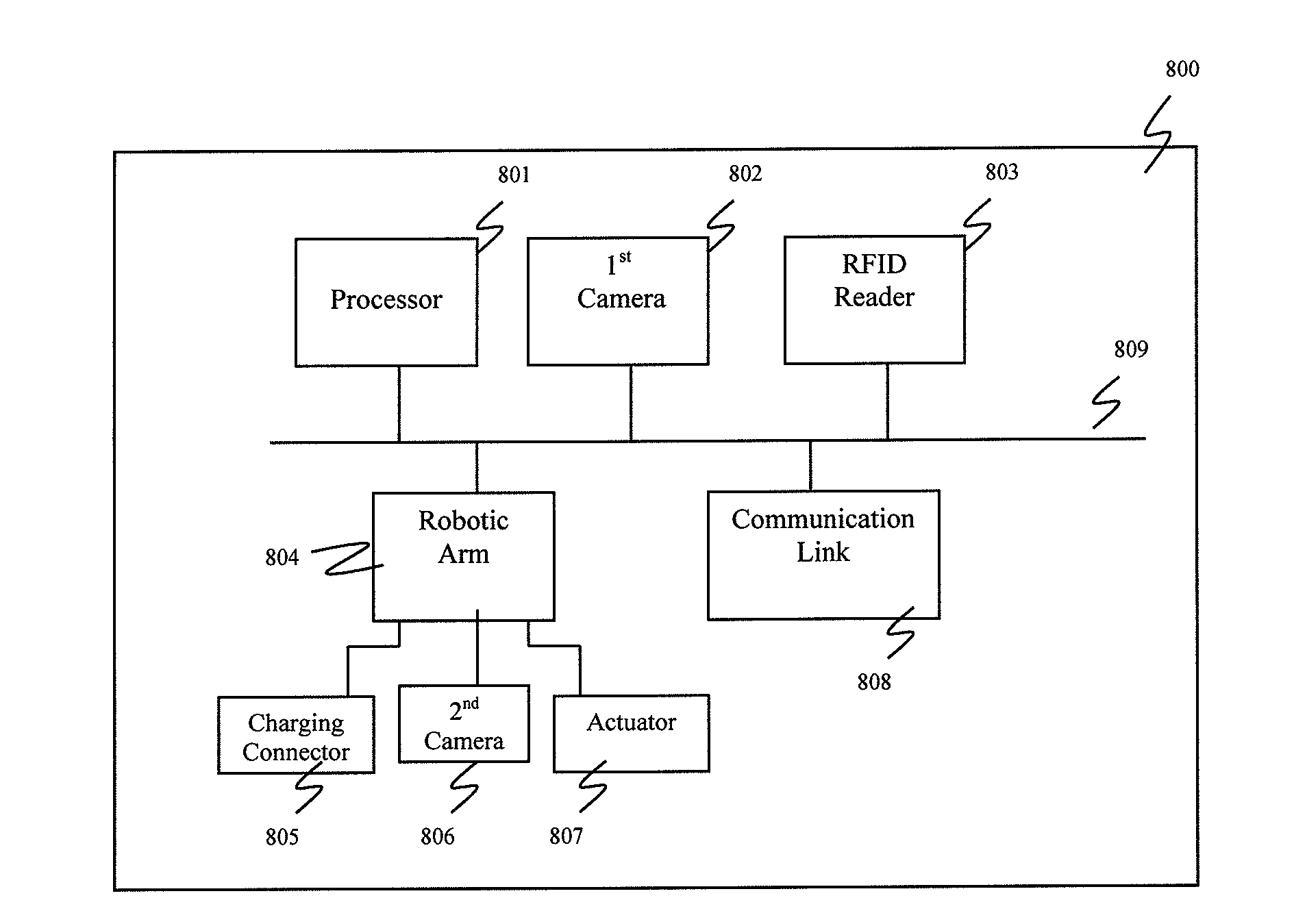
[0021]An exemplary embodiment of an automated electrical vehicle charging system may include a processor, a camera and an associated computer interface board (e.g., a frame grabber), a charging cable and a charging connector, and a robotic arm. The electric vehicle charging station may automatically connect to a vehicle and charge the vehicle without the need for operator action. The charging station may operate without the user having to precisely align the vehicle at the charging station, and without any specialized modifications or equipment installations made to the vehicle. For example, when a vehicle is driven up to and parked near the charging station, the charging system may recognize that the vehicle is present, identify inform...


PUM


Abstract

A system and method for charging an electric vehicle includes identifying vehicle information corresponding to the electric vehicle based on an electronic image of the electric vehicle, retrieving from an electronically stored database a location of a charging port on the electric vehicle based on the vehicle information, and robotically moving a charging connector according to the retrieved location to engage the charging port of the electric vehicle to charge a battery.

Description

CROSS-REFERENCE TO RELATED PATENT APPLICATION[0001]This application claims priority to and the benefit of Provisional Application Ser. No. 61 / 325,643, filed on Apr. 19, 2010, and Provisional Application Ser. No. 61 / 328,411, filed on Apr. 27, 2010, the disclosure of which is incorporated by reference herein in its entirety.TECHNICAL FIELD[0002]The present disclosure relates to automatically charging an electric vehicle, and more particularly, to a system and method for automatically charging an electric vehicle.DISCUSSION OF RELATED ART[0003]With the growing availability of electric vehicles, there will be a need for charging stations to facilitate the operator of an electric vehicle to ‘fill-up’ the electric charge of his vehicle. The operator may have to manually perform certain actions, including charging the vehicle, entering payment information, selecting options (e.g., fast or slow charging), or initiating and / or approving the charging operation. Although a charging station at ...

Claims


Application Information

Patent Timeline
IPC IPC(8): H02J7/00
CPCY02T90/168Y04S30/12Y02T90/169Y04S30/14Y02T90/121B60L11/1827Y02T90/128B60L11/1846Y02T10/7088Y02T10/7005Y02T90/125Y02T90/163Y02T90/14B60L11/1835Y02T10/7072B60L53/35B60L53/37B60L53/65B60L53/665B60L53/18Y02T10/70Y02T90/12Y02T90/167Y02T90/16B60L53/14
Inventor HADDAD, JOSEPH C.LYSAK, DANIEL B.
Owner INTERIM DESIGNS
Learn More