Optical sensing apparatus, filter apparatus, and projector with Anti-dust structure

a technology of optical sensing and filtering, applied in the direction of camera filters, instruments, transportation and packaging, etc., can solve the problems of decreasing achieve the effect of reducing the opportunity reducing the chance for the later dust to deposit, and reducing the air flow passing by the optical sensor

Active Publication Date: 2011-10-20
QUISDA CORP
View PDF1 Cites 2 Cited by
  • Summary
  • Abstract
  • Description
  • Claims
  • Application Information

AI Technical Summary

Benefits of technology

[0008]The stop block is located beside the optical sensor, which obstructs the path of the air flow with dust. Besides, a narrow flow passage is formed between the stagnation surface and the rotation surface, which constrains the path of the air flow without retarding the rotation of the rotation device to reduce the opportunity for the dust to deposit. When the rotation device rotates, the air flow induced by the rotation surface can pass through only the narrow flow passage and most of the dust carried within the air flow stays on the stagnation surface of the stop block. When more and more dust deposits on the stagnation surface, the narrow flow passage is narrower so that it is difficult for the later air flow to flow in; that is, the opportunity for the later dust to deposit decreases.
[0009]Obviously, the air flow passing by the optical sensor has been reduced because of the disposition of the stop block. Based on the design of the stagnation surface of the stop block, most of the dust carried within the air flow deposits on the stagnation surface before the air flow reaches the optical sensor, so as to greatly reduce the dust deposition on the sensing surface of the optical sensor, which increases the normal operation time of the optical sensor.
[0010]Another objective of the invention is to provide a filter apparatus with anti-dust structure. The filter apparatus mainly consists of a color wheel module combined with the optical sensing apparatus of the invention. The color wheel module is disposed on the base and includes the rotation device, such as a color wheel motor. As described above, the filter apparatus of the invention is equipped with the optical sensing apparatus with anti-dust structure, so the optical sensor can operate normally for a long time and the rotation speed of the color wheel motor is therefore controlled stably.
[0011]Another objective of the invention is to provide a projector with anti-dust structure. The projector mainly consists of a housing and the filter apparatus of the invention inside the housing. The housing forms an accommodating space where the components of the filter apparatus are disposed. The housing also forms a plurality of vents for air to pass through. As described above, the filter apparatus of the invention is equipped with the optical sensing apparatus with anti-dust structure, so the rotation speed of the color wheel motor is controlled stably and the projector can therefore project images correctly.
[0012]Compared with the prior art, the optical sensing apparatus, the filter apparatus, and the projector with anti-dust structure of the invention can reduce the deposition amount of the dust on the sensing surface of the optical sensor efficiently without disrupting the cooling effect on the rotation device and so on by the air flow. Therefore, when there is much dust carried within the air flow entering the housing, the optical sensing apparatus, the filter apparatus, and the projector with anti-dust structure can still operate normally, not like a conventional projector which cannot judge the rotation speed of a color wheel correctly due to the optical sensor covered with dust so as not to control the rotation speed of the color wheel properly and project correct images.

Problems solved by technology

When more and more dust deposits on the stagnation surface, the narrow flow passage is narrower so that it is difficult for the later air flow to flow in; that is, the opportunity for the later dust to deposit decreases.

Method used


Image

  • Optical sensing apparatus, filter apparatus, and projector with Anti-dust structure
  • Optical sensing apparatus, filter apparatus, and projector with Anti-dust structure
  • Optical sensing apparatus, filter apparatus, and projector with Anti-dust structure

Examples


Embodiment Construction

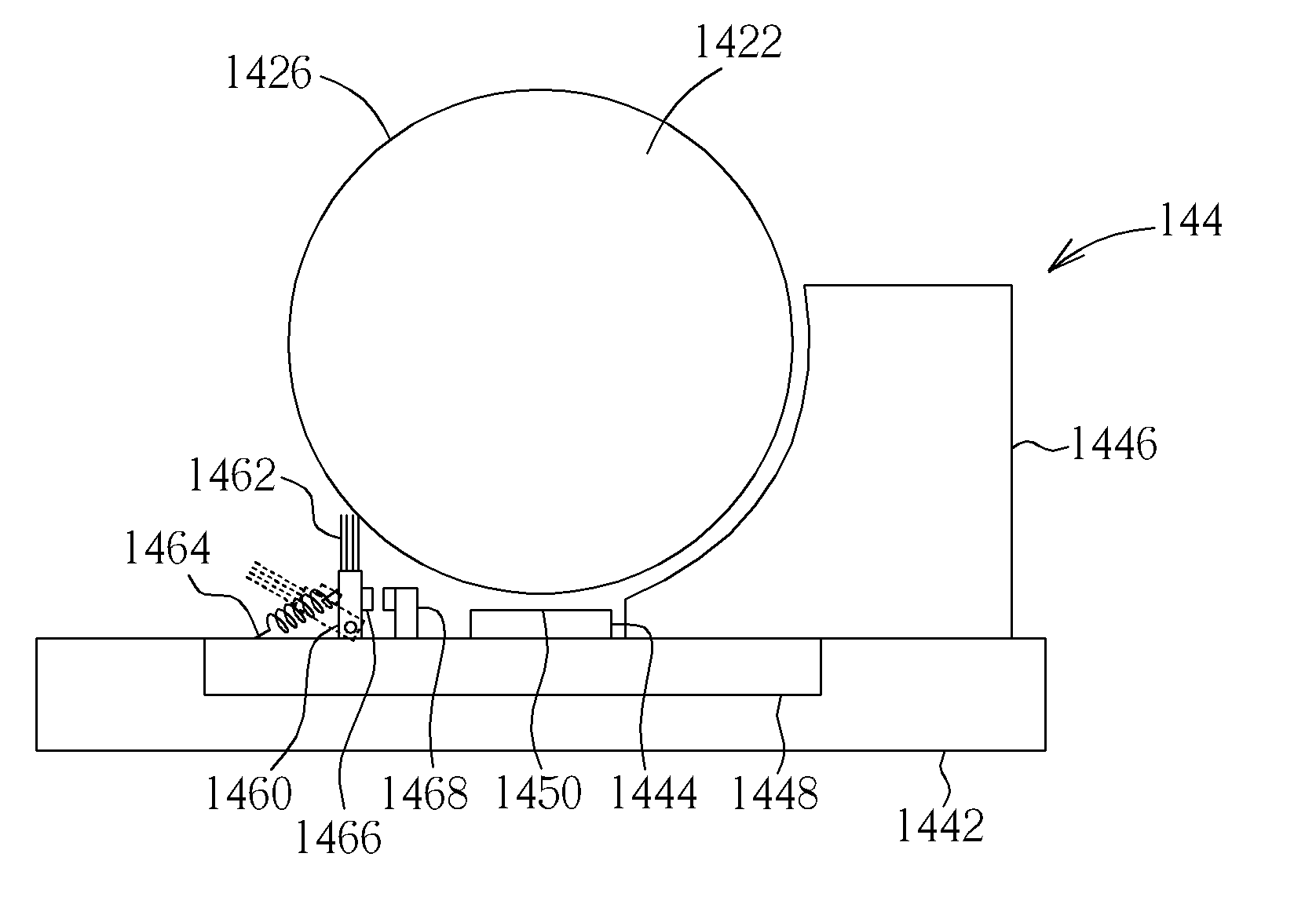
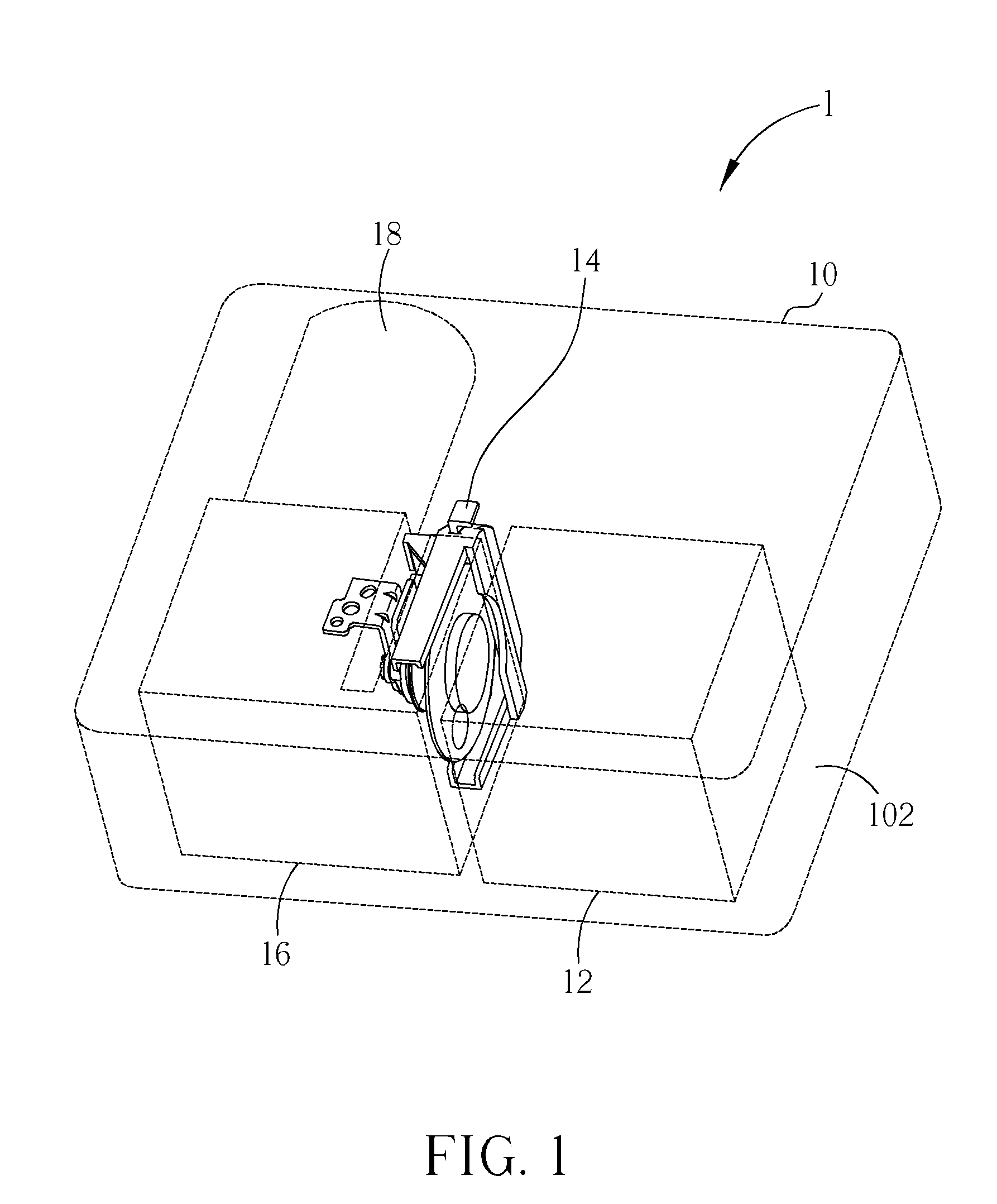
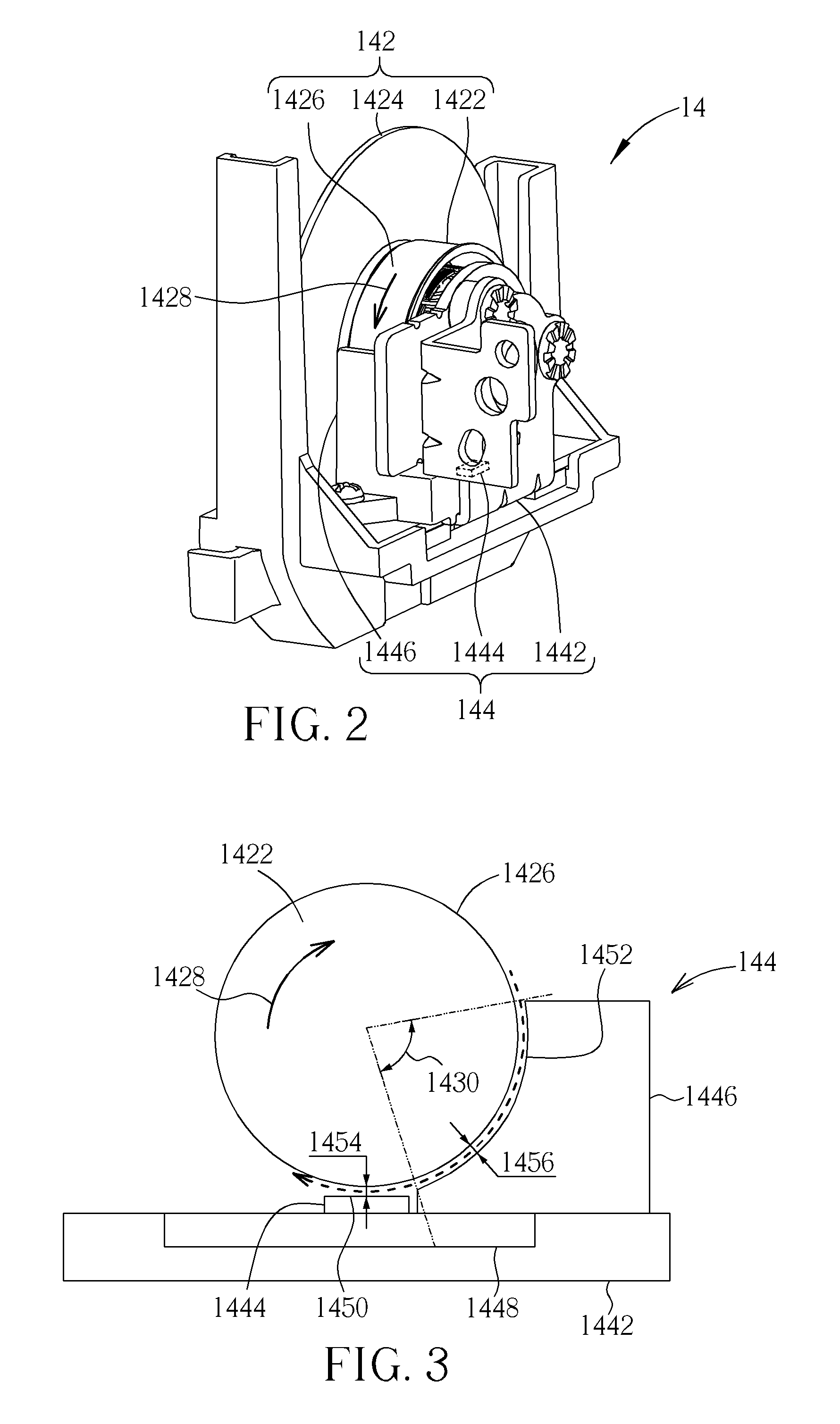
[0022]Please refer to FIG. 1, which is a schematic diagram of an interior structure of a projector 1 according to a preferred embodiment of the present invention. The projector 1 includes a housing 10, a light source apparatus 12, a filter apparatus 14, an optical modification apparatus 16, and a projection lens 18. The housing 10 forms an accommodating space 102 therein for accommodating the light source apparatus 12, the filter apparatus 14, the optical modification apparatus 16, the projection lens 18, and other required electronic components. Light emitted from the light source apparatus 12 passes through the filter apparatus 14 to provide required color lights to the optical modification apparatus 16. The optical modification apparatus 16 can include a digital micro-mirror device (DMD) or a liquid crystal display (LCD) for modifying the color lights to form required images which are projected on a screen through the projection lens 18 later. In order to highlight the position o...


PUM


Abstract

An optical sensing apparatus with anti-dust structure, for sensing a rotation device which has a rotation surface rotating along a rotation direction, includes a base, an optical sensor, and a stop block. The stop block is located beside the optical sensor and disposed with the optical sensor on the base in accordance with the order of the rotation direction. A distance between a stagnation surface of the stop block and the rotation surface is shorter than a distance between a sensing surface of the optical apparatus and the rotation surface. When an air flow passes between the stagnation surface and the rotation surface, dust within the air flow could be partially deposited on the stagnation surface so as to reduce the deposition amount of the dust on the sensing surface. A filter apparatus with the optical sensing apparatus and a projector with the filter apparatus are also disclosed.

Description

BACKGROUND OF THE INVENTION[0001]1. Field of the Invention[0002]The invention relates to an optical sensing apparatus, a filter apparatus, and a projector, and especially relates to an optical sensing apparatus, a filter apparatus, and a projector with anti-dust structure.[0003]2. Description of the Prior Art[0004]As the dependence on electronic equipment of people increases, the adaptability to environment of the electronic equipment is promoted. In general, a housing of electronic equipment generating heat has a plurality of vents formed thereon for air to pass through for taking away heat generated in operation by electronic components inside the housing. However, in some environments, such as arid zones, there is often fine dust floating in the air. The fine dust enters the housing with an air flow, and a part of the dust deposits on the surfaces of the electronic components. This situation does not matter for a general requirement of heat dissipation. But for an electronic comp...

Claims


Application Information

Patent Timeline
Patent Type & Authority Applications(United States)
IPC IPC(8): G03B21/14G02B5/20G01D11/24G03B11/04
CPCG01B11/26G03B33/08G03B21/14G03B11/00
Inventor SHIH, FU-SHIUNGSHEN, CHUN-MING
Owner QUISDA CORP
Why Eureka
Try Eureka