Microwave oscillating element and thin film magnetic head therewith

a technology of micro-oscillating elements and thin film magnetic heads, which is applied in the direction of generators/motors, instruments, record information storage, etc., can solve the problems of large difficulties in technology and cost, difficult to obtain stable oscillation, and deterioration of heat stability

Active Publication Date: 2011-10-20
TDK CORPARATION
View PDF1 Cites 15 Cited by
  • Summary
  • Abstract
  • Description
  • Claims
  • Application Information

AI Technical Summary

Benefits of technology

[0023]In order to resolve the above object, a microwave oscillation element of the present invention includes a lamination main part in which an oscillating layer that is a magnetization free layer and that generates a high frequency electromagnetic field by an excitation of a spin wave, a nonmagnetic intermediate layer, a polarizer layer, and a reference layer that is to be a base magnetic layer of a spin transfer due to application of current are layered in this order, wherein the oscillating layer is made of CoIr; the polarizer layer is configured of CoCr or CoRu; and the nonmagnetic intermediate layer is configured of Cr or Ru.

Problems solved by technology

Therefore, the magnetic microparticles must be made small; however, this causes in a problem that heat stability deteriorates due to a decrease in the volume of the microparticle.
However, both of the first and second methods described above require significantly changes to a conventional magnetic head structure and a recording medium structure, resulting in large difficulties in technology and cost.
However, with only the contents of the art disclosed in documents 1 through 3 described above, it can be said that it is difficult to obtain stable oscillation even at high frequency.
Moreover, it can be said that an improvement in an oscillation efficiency is not particularly expected.
As a result of this, contrary to the expectation of the inventor of the present application, the spin injection efficiency was low.

Method used


Image

  • Microwave oscillating element and thin film magnetic head therewith
  • Microwave oscillating element and thin film magnetic head therewith
  • Microwave oscillating element and thin film magnetic head therewith

Examples


examples

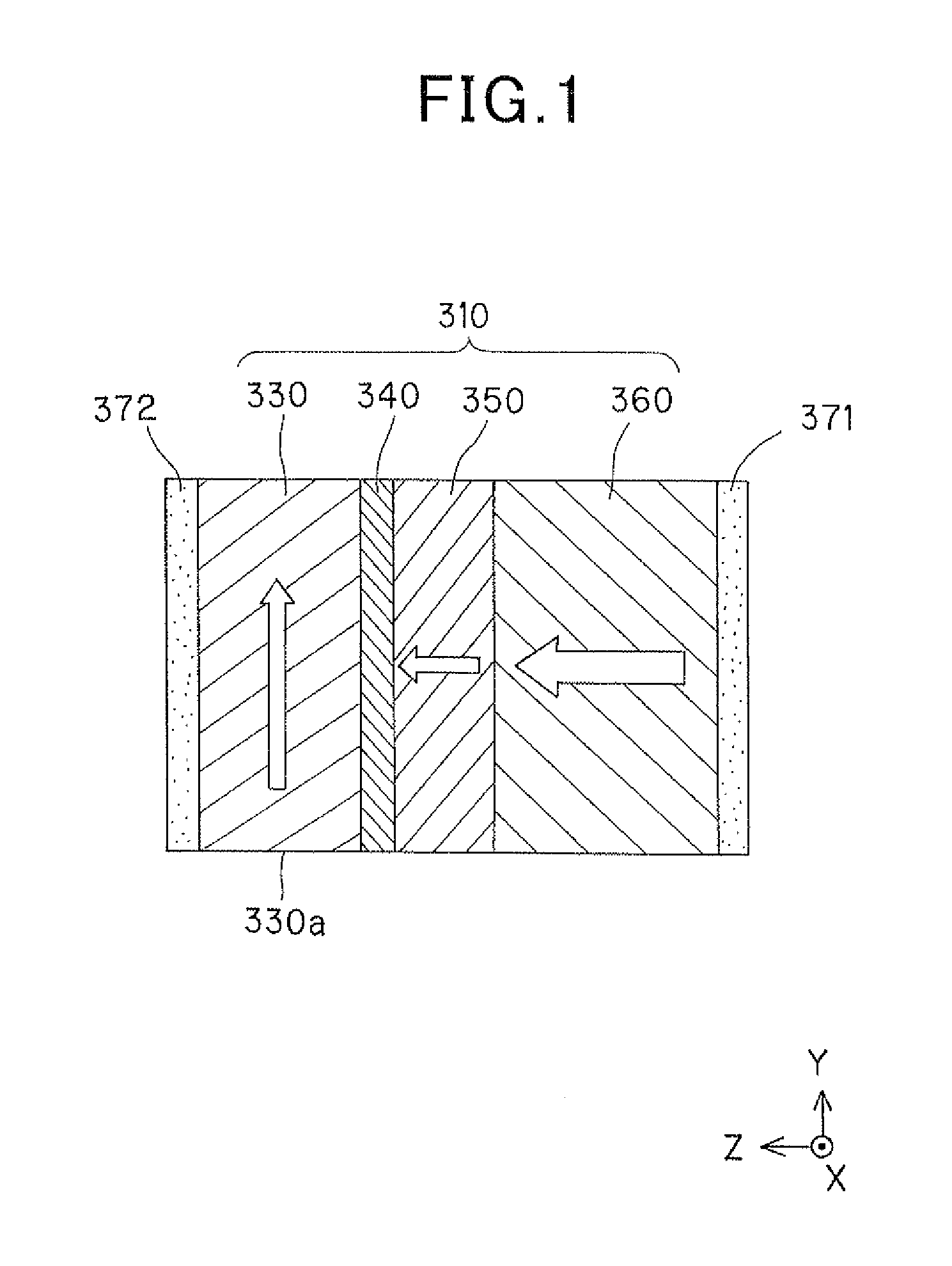
[0163]Further detailed description will be given regarding the above-described invention of the microwave oscillation element with concrete examples, which will be described below.

experimental example i

Example 1

[0164]A microwave oscillation element structured with a lamination structure illustrated in Table 1, which is described below, was formed by a sputtering method, and was used as a sample of example 1 of the present invention.

[0165]An experiment to verify an efficiency of spin injection was executed. In the present experiment, materials of both reference layers 360 of the present invention and comparative examples, which will be described later, were limited to Co70Fe30. This reference layer 360 was combined with the other lamination configuration, and a microwave oscillation element that was substantially a GMR element was formed. GMR ratio of the formed element was measured. An improvement in the efficiency of the spin injection was verified based on the measured value of the GMR ratio. Additionally, increase in the GMR ratio means the improvement of the efficiency of the spin injection of the element configuration.

[0166]In the lamination structure of the microwave oscilla...

example 2

[0170]A material of the nonmagnetic intermediate layer was changed to Cr from example 1, which was described above. A sample of example 2 of the present invention, as illustrated in the following Table 2, was manufactured the same as example 1 except for the material of the intermediate layer.

TABLE 2(Example 2)ThicknessLamination StructureConfiguration Material of Layer(nm)Electrode (371)Au200Reference Layer (360)Co70Fe304Polarizer Layer (350)Co92.5Cr7.53Nonmagnetic IntermediateCr3Layer (340)Oscillating Layer (330)Co80Ir2010Electrode (372)Au200


PUM

PropertyMeasurementUnit
thicknessaaaaaaaaaa
thicknessaaaaaaaaaa
thicknessaaaaaaaaaa

Abstract

A microwave oscillation element of the present invention includes a lamination main part in which an oscillating layer that is a magnetization free layer and that generates a high frequency electromagnetic field by an excitation of a spin wave, a nonmagnetic intermediate layer, a polarizer layer, and a reference layer that is to be a base magnetic layer of a spin transfer due to application of current are layered in this order. The oscillating layer is made of CoIr, the polarizer layer is configured of CoCr or CoRu; and the nonmagnetic intermediate layer is configured of Cr or Ru. As a result, the efficiency of the spin injection is improved and the microwave oscillation element where the oscillation efficiency is excellent can be realized.

Description

BACKGROUND OF THE INVENTION[0001]1. Field of the Invention[0002]The present invention relates to a microwave oscillation element (or microwave oscillator). Particularly, the present invention relates to a microwave oscillation element that is used for irradiating a microwave to a magnetic recording medium and writing data on an irradiated part, and relates to a thin film magnetic head using the same. Additionally, it is possible for the microwave oscillation element of the present invention to be applied to various types of high-frequency devices.[0003]2. Description of Related Art[0004]Regarding to high density of magnetic recording devices, and specifically hard disks incorporated therein as recording mediums, there is a demand for improvement in the performance of thin film magnetic heads.[0005]In the thin film magnetic heads, a composite type thin film magnetic head is widely used. The composite type thin film magnetic head has a structure where a reproducing head having a magne...

Claims


Application Information

Patent Timeline
Patent Type & Authority Applications(United States)
IPC IPC(8): G11B5/127G11B5/48H02N99/00
CPCG11B5/314G11B2005/0024G11B5/6005
Inventor TSUCHIYA, YOSHIHIRONOGUCHI, KIYOSHITAKAHASHI, MIGAKUTSUNODA, MASAKIYO
Owner TDK CORPARATION
Why Eureka
Try Eureka