Apparatus for Producing Three-Dimensional Shaped Product

a technology of three-dimensional shaped products and apparatuses, which is applied in the field of apparatus for producing three-dimensional shaped products, can solve the problems of reducing heating efficiency, reducing cooling efficiency, and unable to smoothly remove from the table an object which has been completely shaped, so as to achieve the effect of reducing the cooling efficiency of the cooling devi

Active Publication Date: 2011-10-20
MATSUURA MACHINERY
View PDF3 Cites 11 Cited by
  • Summary
  • Abstract
  • Description
  • Claims
  • Application Information

AI Technical Summary

Benefits of technology

[0012]An object of the present invention is to provide an apparatus for producing a three-dimensional shaped product in which a base plate is interposed between a portion which is a region to be sintered among individual powder layers and a table, a

Problems solved by technology

Thereby, it is impossible to smoothly remove from the table an object which has been completely shaped.
However, in the conventional technologies, on heating, thermal energy on the base plate is conducted

Method used


Image

  • Apparatus for Producing Three-Dimensional Shaped Product
  • Apparatus for Producing Three-Dimensional Shaped Product
  • Apparatus for Producing Three-Dimensional Shaped Product

Examples


example 1

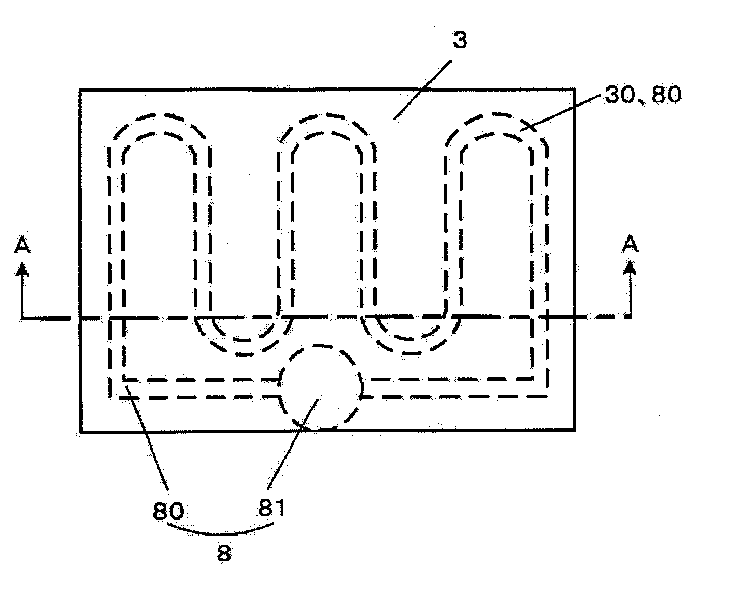
[0062]As shown in FIG. 1, Example 1 is characterized in that, in the basic configuration (2), a base 91 does not cover ½ or more of an upper part of an HC pipe 80 on the basis of the height direction thereof, and a recess 30 provided below a base plate 3 is fitted into the upper part of the HC pipe 80. (In FIG. 1, constituents used in firmly fixing the HC apparatus 8 such as a leg part 5, a frame body or a supporting rod 7 are not illustrated.)

[0063]As long as the base plate 3 has already loaded a substantial amount of powder 12 on the upper part thereof in the step (a) and the powder 12 has been sintered in the step (b), a substantial weight acts on the HC pipe 80 from the base plate 3.

[0064]Therefore, the recess 30 is fitted into the HC pipe 80, by which the base plate 3 of the HC apparatus 8 is installed stably. As described in the embodiments of FIGS. 5 and 6, there is no need for fixing the base plate 3 to the HC apparatus 8 with a fixing bolt 6 and others, which is quite conve...

example 2

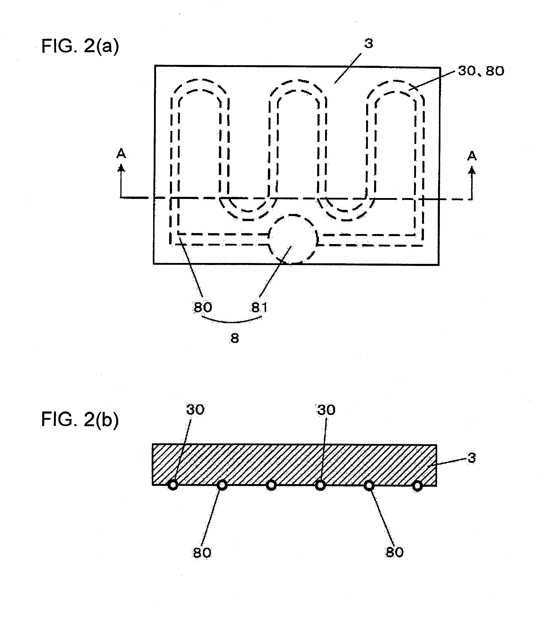
[0065]As shown in FIG. 2, Example 2 is characterized in that, in the basic configuration (3), the upper part of the HC pipe 80 is not covered and the recess 30 provided below the base plate 3 is fitted into the upper part of the HC pipe 80. (In FIG. 1, constituents used in firmly fixing the HC apparatus 8 such as the support 4, the frame body or the supporting rod 7 are not illustrated.)

[0066]On the basis of grounds similar to that of Example 1, in Example 2 as well, the base plate 3 can be supported stably on the HC apparatus 8. There is no need for firmly fixing the base plate 3 to the HC apparatus 8 with a fixing bolt 6 and others, which is quite convenient.

example 3

[0067]As shown in FIG. 3, Example 3 is characterized in that an inclined state which sequentially lowers is formed on the table 2 and a discharge opening 21 for discharging the powder 12 which has not been sintered is provided at a lower end part of the inclined part.

[0068]Where the powder 12 is loaded on the table 2 and the surface of the base plate 3, all the powder 12 is not necessarily subjected to sintering.

[0069]In this case, the powder 12 which is not sintered remains inevitably at the lower part of the table 2, after the shaped article 13 is taken out above from the table 2, together with the base plate 3.

[0070]In Example 3, the remaining powder 12 comes down along a lower part of the inclined part and can be discharged into the lower part of the shaping tank 1 via an opening located at the lowest position. It is, therefore, possible to reuse the powder 12.

[0071]In order to exhibit the effect of Example 3 as much as possible, as shown in FIG. 3, it is preferable that the end...


PUM

PropertyMeasurementUnit
Lengthaaaaaaaaaa
Heightaaaaaaaaaa
Thermal conductivityaaaaaaaaaa

Abstract

An apparatus for producing a three-dimensional shaped product capable of decreasing thermal dissipation due to thermal conduction of a heating device or a cooling device loading a base plate, in which powder is sequentially sintered on a table and a base plate a inside a shaping tank wherein a space of vertical direction is formed on the table or the space is formed and a heat insulating material is filled into the thus formed region, a heating device or a cooling device which loads the base plate a supporting the sintered layer is firmly fixed.

Description

FIELD OF THE INVENTION[0001]The present invention relates to an apparatus for producing a three-dimensional shaped product in which metal powder or non-metal powder loaded on a vertically movable table is laminated while being sintered by irradiating electromagnetic waves to each layer, thereby producing a predetermined three-dimensional shaped product.DESCRIPTION OF THE RELATED ART[0002]There have been proposed various configurations in technical fields where metal powder or non-metal powder is sintered by irradiation of electromagnetic waves such as laser beams or electron beams, thereby molding a three-dimensional shaped product. However, any configuration will always entail the following steps:(a) a planarization step for spraying powder by allowing the powder to fall and sliding on the upper-side surface or in the vicinity of the thus sprayed powder,(b) a step in which a region to be shaped is irradiated by electromagnetic waves such as laser beams or electron beams, thereby si...

Claims


Application Information

Patent Timeline
IPC IPC(8): B22F3/00B29C35/08
CPCB22F3/105B29C67/0092B29C67/0077B29C64/153B29C64/40B33Y30/00B33Y10/00Y02P10/25
Inventor AMAYA, KOICHIURUSHIZAKI, YUKINORIMATSUBARA, HIDETO
Owner MATSUURA MACHINERY
Why Eureka
Try Eureka