System for positioning on a patient an observation and/or intervention device

a technology for positioning and patient, applied in the field of system for positioning on a patient an observation and/or intervention device, can solve the problems of difficult to impose significant movements to the trocar, difficult to access the abdomen of the patient, and complex,

Inactive Publication Date: 2011-10-20
UNIV JOSEPH FOURIER
View PDF4 Cites 24 Cited by
  • Summary
  • Abstract
  • Description
  • Claims
  • Application Information

AI Technical Summary

Benefits of technology

The present invention provides a system, taking up a small volume, for positioning on a patient's body an observation and/or intervention device having a portion penetrating into the pat...

Problems solved by technology

Such systems are generally formed of massive, complex, and expensive robots comprising a base attached to the ground and an arm handling the endoscope.
Further, the robot's arm maintaining the endoscope may hinder the access to the patient's abdomen.
A disadvantage of such a system is the difficulty to impose significant movements to the trocar.
Indeed, in the case where the actuators are placed directly on the mount, the volume taken up by the actuators limits the trocar movements.
A difficulty then results, in large ...

Method used


Image

  • System for positioning on a patient an observation and/or intervention device
  • System for positioning on a patient an observation and/or intervention device
  • System for positioning on a patient an observation and/or intervention device

Examples


first embodiment

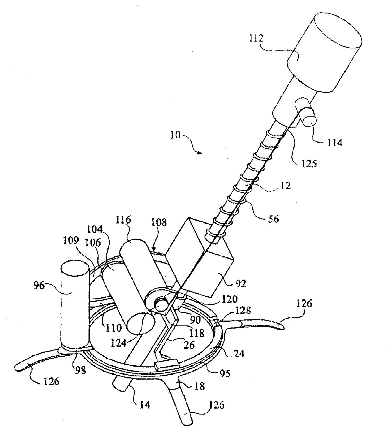
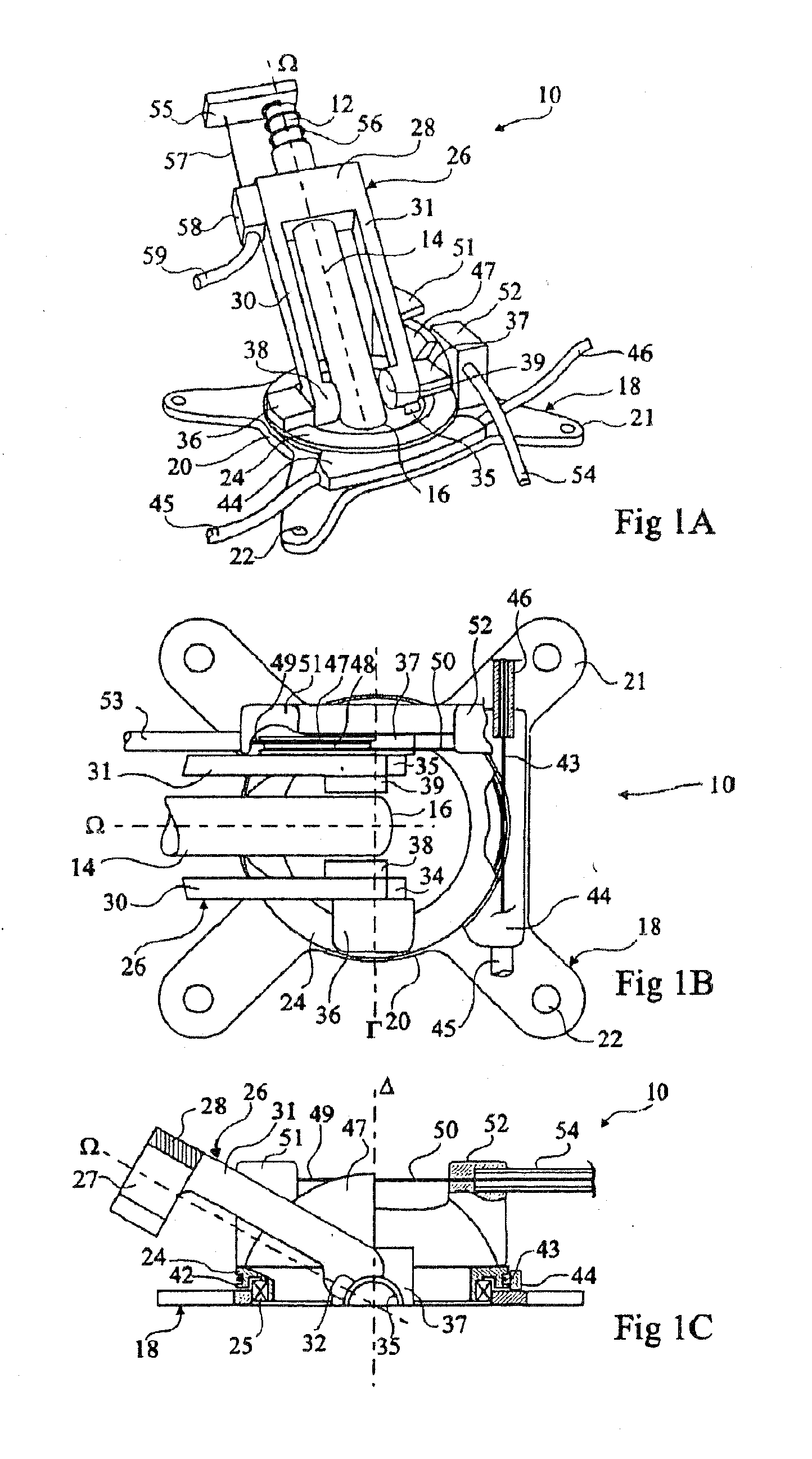
FIGS. 1A to 1C show a system 10 for positioning an endoscope 12 placed in a trocar 14, endoscope 12 and trocar 14 penetrating into a patient's abdomen through a small incision 16. Endoscope 12 has the aspect of a cylindrical tube of axis Ω of a length of some forty centimeters and of a diameter of a few centimeters. In FIG. 1B, a portion only of trocar 14 is shown. In FIG. 1C, only axis Ω of endoscope 12 is shown. A camera, not shown, is attached to the end of endoscope 12 external to the abdomen.

System 10 comprises a substantially planar base 18 comprising a planar ring-shaped central portion 20, surrounding incision 16, from which four arms 21 extend. A cylindrical opening 22 is formed at the end of each arm 21. Openings 22 may be used to maintain base 18 on the patient's body via straps, cables, etc. attached to the table on which the patient is laid or directly attached to the patient. Base 18 may also be glued on the patient's abdomen.

Central annular portion 20 supports a mobil...

second embodiment

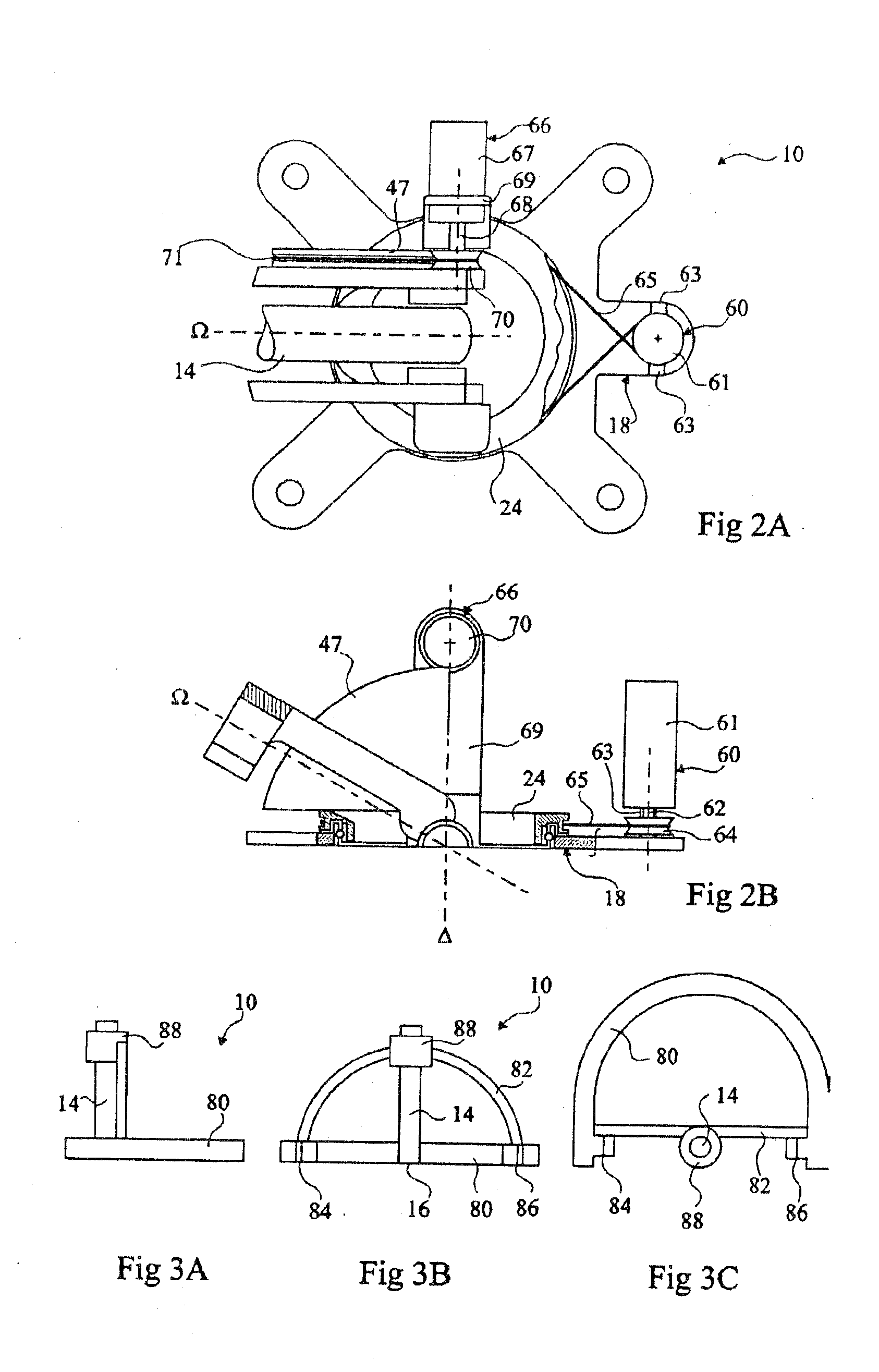
FIGS. 3A to 3C very schematically show system 10 for positioning trocar 14 in which the endoscope (not shown) slides, the trocar and the endoscope penetrating into the patient's abdomen through incision 89.

According to the second embodiment, system 10 comprises a “C”-shaped base 80 resting on the patient's abdomen. A semi-circular rail 82 is pivotally assembled on base 80 around an axis substantially tangent to the patient's abdomen. The two ends of rail 82 are substantially connected to the two ends of base 80 by two pivotal connections 84, 86. A carriage 88 is slidably assembled on rail 82. Carriage 88 supports trocar 14.

The means for controlling the sliding of the endoscope in trocar 14 are not shown in FIGS. 3A to 3C and may be identical to those of the first embodiment.

The sliding of carriage 88 on rail 82, and the pivoting of rail 82 with respect to base 80, may be controlled by cable driven by actuators placed at a distance from the patient as for the first embodiment, or by ...


PUM


Abstract

The present invention relates to a system for positioning with respect to a patient's body an observation and/or intervention device having a portion penetrating into the patient's body comprising a base laid on the patient's body; a means for supporting the device formed of a first portion movably assembled on the base according to a connection with one degree of freedom, and of a second portion movably assembled on the first portion according to a connection with one degree of freedom and connected to the device; and means for actuating the first portion with respect to the base, and the second portion with respect to the first portion, in which the base surrounds at a distance at least partially the device, said device being detachably connected to the second portion to enable removal of the positioning system while leaving in place the device.

Description

FIELD OF THE INVENTIONThe present invention relates to a system for positioning on a patient an observation and / or intervention device having a portion penetrating into the patient's body. It for example applies to medical analysis systems, such as endoscopic systems, and it will more specifically be described in the case of a use of an endoscope in a laparoscopy.BACKGROUNDIn such a type of operation, an endoscope formed of a thin optical tube is inserted into the patient's abdomen through a small incision performed at the level of the patient's abdomen. The optical tube is generally connected to an external video camera. Other incisions may be performed to introduce surgical instruments handled by a surgeon. The endoscope is used to visualize the patient's internal organs and the surgical instruments. Since the surgeon generally has both hands occupied by the surgical instruments, an assistant is necessary to maintain the endoscope in a desired position.Robotic systems have been de...

Claims


Application Information

Patent Timeline
IPC IPC(8): A61B1/00A61B17/00A61B17/34A61B19/00
CPCA61B19/22A61B19/201A61B17/3403A61B2017/3409A61B19/26Y10S901/19B25J18/00A61B2017/3407Y10T74/20305A61B19/5244A61B2017/00398A61B19/5212A61B34/20A61B34/70A61B90/361A61B90/50A61B90/11
Inventor BERKELMAN, PETERCINQUIN, PHILIPPEJACQUET, ALAINARNAULT, JEAN
Owner UNIV JOSEPH FOURIER
Why Eureka
Try Eureka