Method and an Apparatus for Manufacturing an Optical Lens

a manufacturing method and optical lens technology, applied in the field of optical lens manufacturing, can solve problems such as incorrect positioning of one surface, and achieve the effect of respecting the optical properties of the desired lens

Active Publication Date: 2011-10-20
ESSILOR INT CIE GEN DOPTIQUE
View PDF8 Cites 42 Cited by
  • Summary
  • Abstract
  • Description
  • Claims
  • Application Information

AI Technical Summary

Benefits of technology

[0010]By compensating in such a manner for errors in positioning, the optical quality of machined optical lens can be improved, particularly in the manufacture of dual side lens by reducing the dispersion related to the blocking stage of the manufacturing operation. This dispersion can result from incorrect positioning of one surface of an optical lens with respect to an opposing surface.

Problems solved by technology

This dispersion can result from incorrect positioning of one surface of an optical lens with respect to an opposing surface.

Method used


Image

  • Method and an Apparatus for Manufacturing an Optical Lens
  • Method and an Apparatus for Manufacturing an Optical Lens
  • Method and an Apparatus for Manufacturing an Optical Lens

Examples


first embodiment

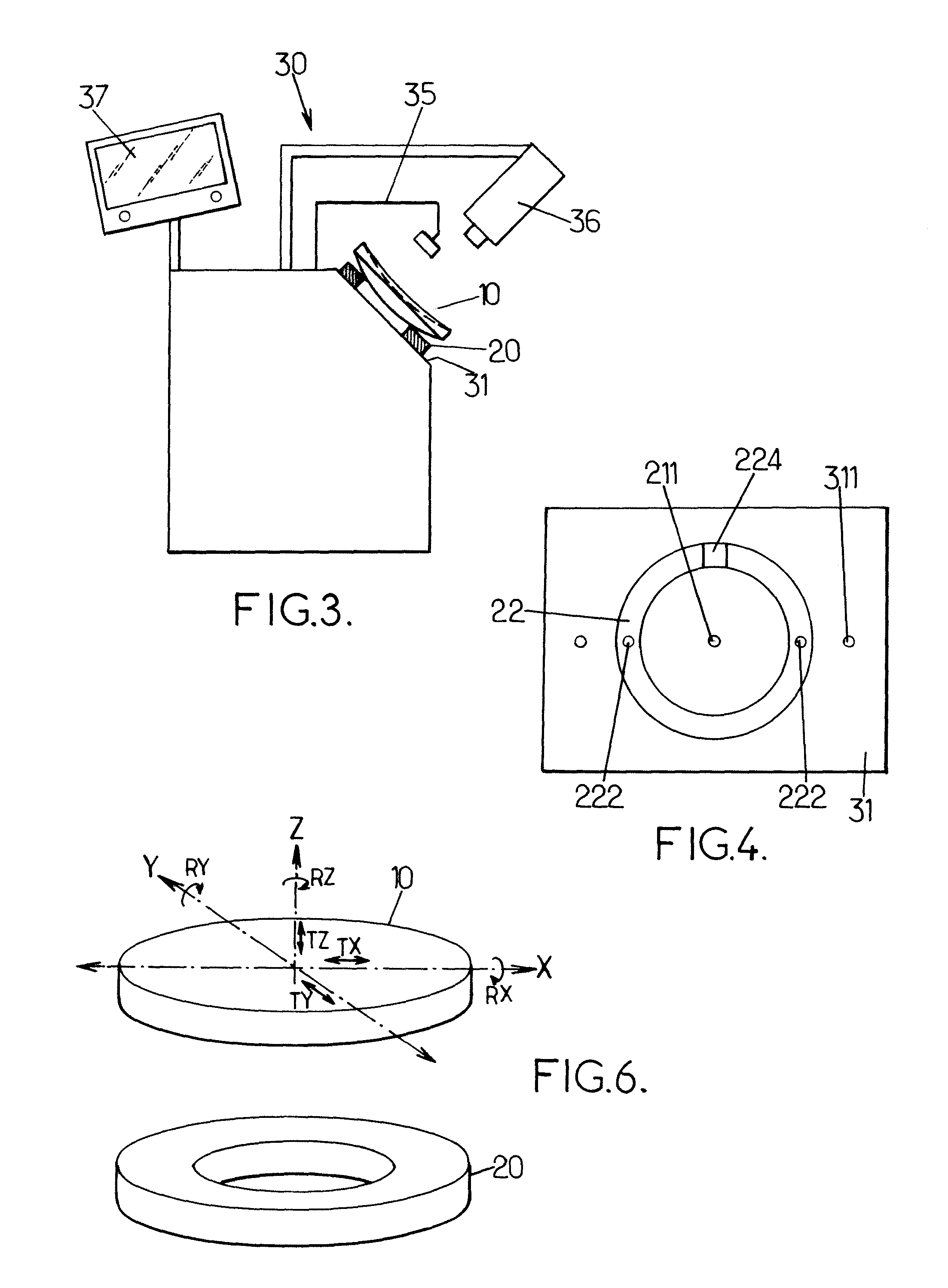
[0042]a method and apparatus of manufacturing an optical lens from a semi finished lens will be described with reference to FIGS. 1A to 8B.

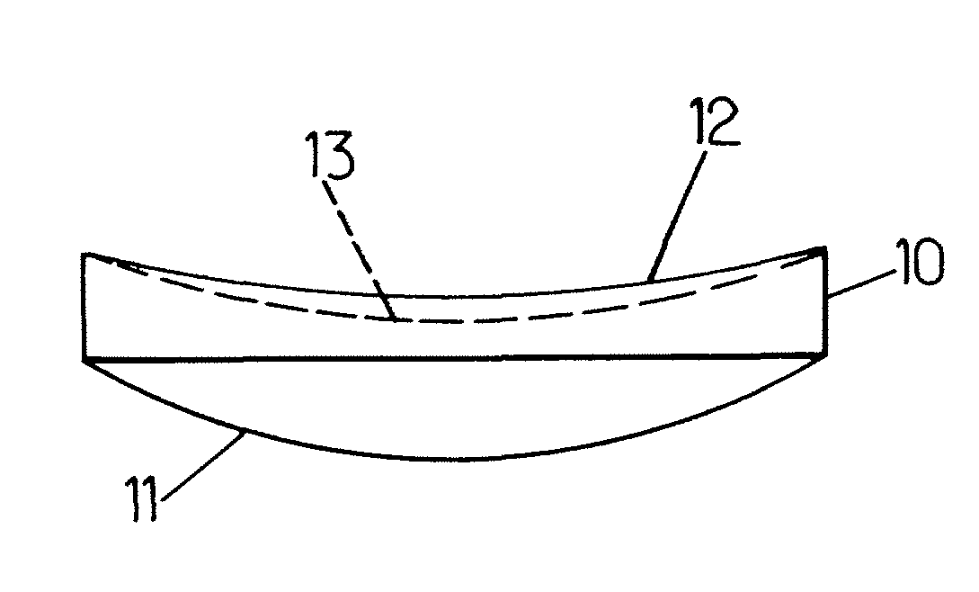
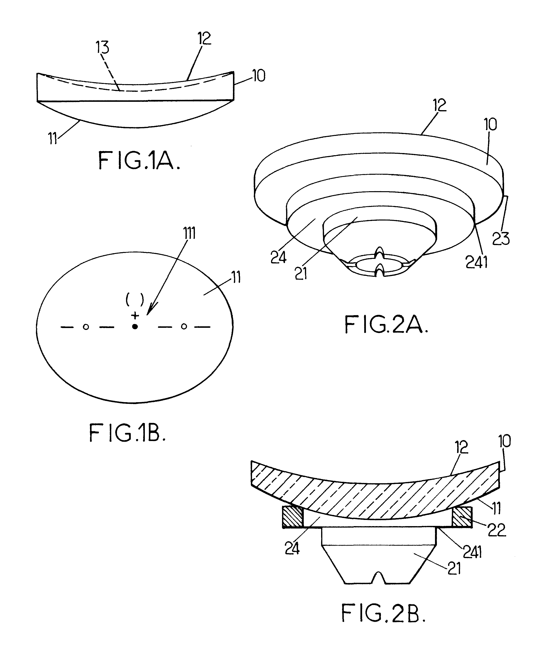
[0043]Semi finished lens member 10 has a preformed front surface 11 that, in use of the resulting finished optical lens, is disposed nearest the object being viewed and an opposing surface 12 to be modified by the manufacturing process to provide the back surface 13 of the finished optical lens, represented by the dotted line. Opposing surface 12 is machined by a machining tool so that the back surface 13 is orientated with respect to and distanced from the front surface 12, according to the required optical prescription. While in this embodiment of the invention, the back surface of the optical lens is formed by the machining process, it will be understood, that in alternative embodiments of the invention both or either surfaces of the lens may be formed by the machining process. Moreover, although the optical surface 13 to be manufactured is re...

second embodiment

[0070]the invention will now be described with reference to FIGS. 10 to 12.

[0071]In this embodiment of the invention lens member 10 which is similar to semi finished lens member 10 of the previous embodiment is mounted on a prismatic blocking device 40 as illustrated in FIG. 10.

[0072]Prismatic blocking device 40 enables the lens device to be supported at a given inclination or tilt for the machining process and comprises casting block 45 having a recessed housing 46 in which blocking preform 41 is housed, and a blocking ring 42. Preform 41 may be inclined at an angle a to the vertical axis. Blocking cast material 44 is poured into the cavity 47 defined by the front surface 11 of the optical lens 10, housing 46 and inclined preform 41. When cooled the blocking cast material 44 solidifies to support the optical lens 10 at the desired prismatic orientation for machining. The lower surface or bearing surface 441 of blocking material 441 acts as a reference surface. Blocking device 40 is...

case iii

[0084]The methods of the embodiments of the invention compensating for an positioning error rather than repositioning a lens member in order to reduce the error. There is no impact on the actual blocking operation since the compensation is performed by software, and thus no modifications to the physical blocking equipment are necessary for the methods to be implemented. The acceptable tolerances for positioning errors may be increased since the errors are compensated for. FIG. 13 illustrates what may happen when the machined surface is incorrectly positioned with respect to a preformed surface in the manufacture of an optical lens. In FIG. 13 the generation of the back surface 13 with respect to the front surface 11 is shown for[0085]case I where the lens member is placed at the correct positioning with respect to the blocker 21—in this case the back surface 13 is correctly orientated with respect to and distanced from the front surface 11 according to the optical prescription[0086]...


PUM

PropertyMeasurementUnit
optical propertiesaaaaaaaaaa
degrees of freedomaaaaaaaaaa
shapeaaaaaaaaaa

Abstract

A method of manufacturing an optical lens, the method comprising the steps of blocking a lens member at a first positioning on a blocker; determining the first positioning of the lens member with respect to the blocker; comparing the first positioning of the lens member with a predetermined positioning in order to determine a positioning error between the first positioning and the predetermined positioning; determining a surface positioning of the surface to be manufactured with respect to the blocker according to the positioning error; and configuring operational parameters of a lens manufacturing tool in order to manufacture a surface according to the determined surface positioning such that the desired optical properties of the optical lens are respected. The invention further relates to an apparatus for manufacturing an optical lens.

Description

RELATED APPLICATIONS[0001]This is a U.S. National Phase Application under 35 USC 371 of International Application PCT / EP2009 / 067730 filed on Dec. 22, 2009.[0002]This application claims the priority of European Application No. 08305999.8 filed Dec. 22, 2008, the entire content of which is hereby incorporated by reference.FIELD OF THE INVENTION[0003]The present invention relates to a method of manufacturing an optical lens. Particularly, but not exclusively, the invention relates to a method of blocking an optical lens at a positioning for manufacturing of the lens. The invention further relates to an apparatus for manufacturing an optical lens.BACKGROUND OF THE INVENTION[0004]An optical lens is typically made of plastic or glass material and generally has two opposing surfaces which co-operate with one another to converge or diverge light according to a required corrective prescription. When the positioning or shape of one of these surfaces with respect to the other is inaccurate, op...

Claims


Application Information

Patent Timeline
Patent Type & Authority Applications(United States)
IPC IPC(8): G06F15/00B23Q3/00
CPCB24B13/005Y10T29/49998B29D11/00009B24B47/225B29D11/00942B29D11/00961B29D11/00B24B13/00B24B47/22B24B49/12
Inventor GOURRAUD, ALEXANDRE
Owner ESSILOR INT CIE GEN DOPTIQUE
Why Eureka
Try Eureka