LED backlight driving module

a driving module and led backlight technology, applied in the direction of electric variable regulation, process and machine control, instruments, etc., can solve the problems of poor dynamic contrast, -type led backlight cannot be performed two-dimensional partial dimming, and backlight requires more led units and driving modules, etc., to achieve the effect of reducing design costs

Active Publication Date: 2011-10-27
LITE ON TECH CORP +1
View PDF4 Cites 26 Cited by
  • Summary
  • Abstract
  • Description
  • Claims
  • Application Information

AI Technical Summary

Benefits of technology

[0022]2. The driving m...

Problems solved by technology

However, the direct-type LED backlight requires more LED units and more complicated driving modules.
However, the edge-type LED backlight can not be performed two-dimensional parti...

Method used


Image

  • LED backlight driving module
  • LED backlight driving module
  • LED backlight driving module

Examples


Embodiment Construction

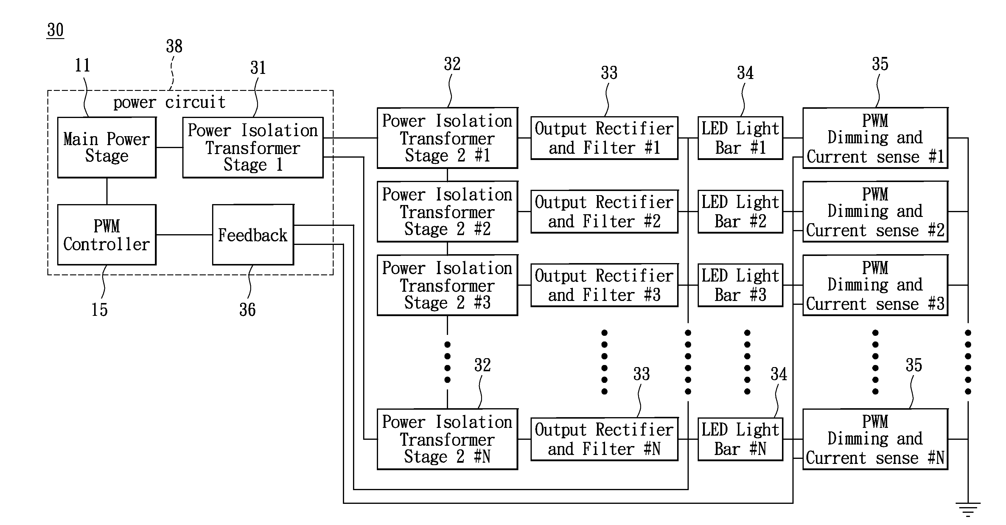
[0037]Reference is made to FIG. 3 illustrating a first embodiment of the LED backlight driving module30 in accordance with the instant disclosure. The driving module 30 includes a main power stage 11, a first stage isolation transformer unit, a second stage isolation transformer unit, a plurality of output rectifiers and filters (#1, #2, #3 . . . #N) 33, a plurality of LED light bars (#1, #2, #3 . . . #N) 34, a plurality of PWM Dimming and Current sensors (#1, #2, #3 . . . #N) 35, a feedback circuit 36, and a PWM controller 15.

[0038]The first stage isolation transformer unit is preferably a first power isolation transformer 31, and the second stage isolation transformer unit is preferably a plurality of second power isolation transformers 32. The power circuit 38 includes the main power stage 11, the first power isolation transformer 31, the feedback circuit 36, and a PWM controller 15. The main power stage 11 may be a generator or a receiver of high-voltage direct current power sig...


PUM


Abstract

The instant disclosure relates to a LED backlight driving module. The driving module utilizes a plurality of second power isolation transformers interconnected to each other in series and connected to a secondary winding of a first power isolation transformer in parallel to produce a plurality of second driving signals with uniform current, and driving corresponding LED light bars with uniform brightness. Optionally, a base voltage circuit can be used to provide a base voltage with negative voltage level on the other end of LED light bars, so as to lower the positive voltage level of the second driving signals. Thus, it is beneficial that the LED backlight driving module provides higher power conversion efficiency and has lower design cost.

Description

BACKGROUND OF THE INVENTION[0001]1. Field of the Invention[0002]The instant disclosure relates to an LED backlight driving module, in particular, the invention relates to a LED backlight driving module having a uniform current output in each LED light bar.[0003]2. Description of Related Art[0004]In recent years, LED backlight is being increasingly applied to the fabrication of large-size LCD display apparatus. Furthermore, the LED backlight provides a solution to environmental protection and power saving since the LED devices do not contain heavy metals such as mercury. Relevant statistics shows that the LED backlight technology is rapidly replacing traditional backlight units with a growing market penetration rate from 3% in 2009 to 20% in 2010.[0005]Currently, LED backlight units can be categorized into direct type and edge type. The direct-type LED backlight units have the advantage of partial light dimming capability to comply with specific video requirements, thus achieving bet...

Claims


Application Information

Patent Timeline
IPC IPC(8): H05B37/02H05B44/00
CPCG09G3/3406H05B33/0815G09G2320/064H05B45/382H05B45/325H05B45/14G09G3/36H05B45/00H05B45/37
Inventor CHEN, WEN-SHENGLIU, CHIH-LUNGCHIU, MING-AN
Owner LITE ON TECH CORP
Why Eureka
Try Eureka