Method for pseudo-differential transmission using a non-uniform interconnection

a transmission method and non-uniform technology, applied in the direction of line transmission details, cross-talk reduction, waveguides, etc., can solve the problems of limited bandwidth, substantial reflection of signals, and limited length l of interconnection

Inactive Publication Date: 2011-10-27
ZXNOISE LLC
View PDF5 Cites 10 Cited by
  • Summary
  • Abstract
  • Description
  • Claims
  • Application Information

AI Technical Summary

Problems solved by technology

In this case, substantial reflections of signals occur, and the specialists know that this implies limitations on the length L of the interconnection (L must be sufficiently small) and on the available bandwidth.
This implies that it is a priori not possible to model propagation in the interconnection using a uniform multiconductor transmission line having n+2=6 conductors, a uniform multiconductor transmission line being a multiconductor transmission line having uniform electrical characteristics over its length.
These articles show that this method does not provide a reduction of internal crosstalk.
Unfortunately, whenever an interconnection cannot be modeled, in a suitable part of the frequency band used for transmission, taking into account the lumped impedances seen by the interconnection and caused by the circuits connected to the interconnection elsewhere than at the ends of the interconnection, as a (n+1)-conductor uniform multiconductor transmission line using the natural voltages referenced to the return conductor and the natural currents as natural electrical variables, the methods disclosed in said French patent applications number 07 / 05260, number 08 / 04429 and number 08 / 04430, and the corresponding international applications, cannot be used and it can be shown that the propagation of signals generates reflected waves from within the interconnection, such reflections producing echo and internal crosstalk.

Method used


Image

  • Method for pseudo-differential transmission using a non-uniform interconnection
  • Method for pseudo-differential transmission using a non-uniform interconnection
  • Method for pseudo-differential transmission using a non-uniform interconnection

Examples


first embodiment

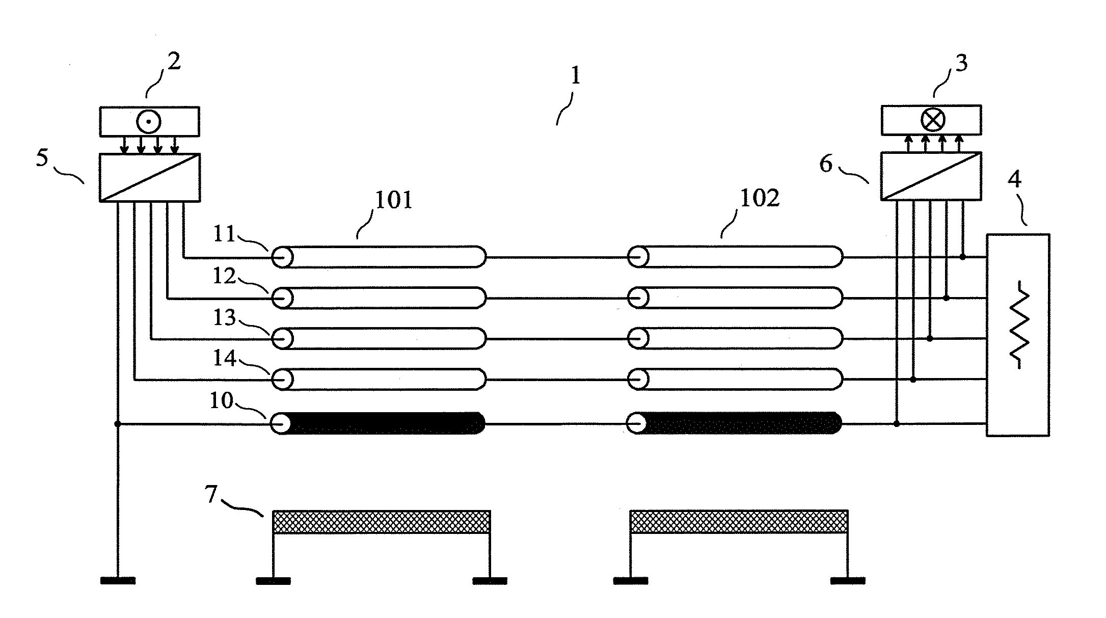
[0148]As a first embodiment of a device for implementing the method of the invention, given by way of non-limiting example, we have represented in FIG. 5 a device of the invention comprising an interconnection (1) having n=4 transmission conductors (11) (12) (13) (14) and a return conductor (10) distinct from a reference conductor (7). A transmitting circuit (5) receives at its input the m=4 “input signals of the transmitting circuit” from the m channels of the source (2). The transmitting circuit (5) comprises n output terminals which are connected to the transmission conductors (11) (12) (13) (14) of the interconnection (1), at the near-end of the interconnection (1). The return conductor (10) is grounded at the near-end of the interconnection (1). A termination circuit (4) is connected to the conductors (10) (11) (12) (13) (14) of the interconnection (1), at the far-end of the interconnection (1). A receiving circuit (6) has its n+1 input terminals connected to the conductors (10...

second embodiment

[0160]As a second embodiment of a device for implementing the method of the invention, given by way of non-limiting example, we have represented in FIG. 12 a device of the invention comprising an interconnection (1) having n=2 transmission conductors (11) (12) and a return conductor (10) distinct from a reference conductor (7). A transmitting circuit (5) receives at its input the m=2 “input signals of the transmitting circuit” from the m channels of the source (2). The transmitting circuit (5) comprises n output terminals which are connected to the transmission conductors (11) (12) of the interconnection (1), at the near-end of the interconnection (1). The return conductor (10) is grounded at the near-end of the interconnection (1). A termination circuit (4) is connected to the conductors (10) (11) (12) of the interconnection (1), at the far-end of the interconnection (1). A receiving circuit (6) has its n+1 input terminals connected to the conductors (10) (11) (12) of the interconn...

third embodiment (

Best Mode)

[0172]As a third embodiment of a device for implementing the method of the invention, given by way of non-limiting example and best mode of carrying out the invention, we have represented in FIG. 13 a device of the invention comprising an interconnection (1) having n=4 transmission conductors (11) (12) (13) (14) and a return conductor (10) distinct from a reference conductor (7). A transmitting circuit (5) receives at its input the m=4 “input signals of the transmitting circuit” from the m channels of the source (2). The transmitting circuit (5) comprises n+1 output terminals which are connected to the conductors (10) (11) (12) (13) (14) of the interconnection (1), at the near-end of the interconnection (1). A termination circuit (4) is connected to the conductors (10) (11) (12) (13) (14) of the interconnection (1), at the far-end of the interconnection (1). A receiving circuit (6) has its n+1 input terminals connected to the conductors (10) (11) (12) (13) (14) of the inte...


PUM


Abstract

The invention relates to a method and a device for pseudo-differential transmission through interconnections used for sending a plurality of electrical signals.
An interconnection having 4 transmission conductors and a return conductor distinct from the reference conductor cannot be modeled as a uniform multiconductor transmission line. Each end of the interconnection is connected to a termination circuit. Three damping circuits are connected between the return conductor and the reference conductor. The transmitting circuits receive at their inputs the signals from the 4 channels of the two sources, and are connected to the interconnection. The receiving circuits are connected to the interconnection, each receiving circuit being such that the signals of the 4 channels of a source connected to a transmitting circuit in the activated state are sent to the four channels of the destinations, without noticeable echo, internal crosstalk and external crosstalk.

Description

CROSS REFERENCE TO RELATED APPLICATIONS[0001]This is a Continuation Application of PCT application PCT / IB2010 / 051863, filed 28 Apr. 2010, published in English under No. WO 2011 / 036573, which in turn claims priority to French patent application No. 09 / 04611 filed 28 Sep. 2009 and entitled “Procédé de transmission pseudo-différentiel utilisant une interconnexion non uniforme”, both of which are incorporated herein by reference.FIELD OF THE INVENTION[0002]The invention relates to a method and a device for pseudo-differential transmission through interconnections used for sending a plurality of electrical signals, such as the interconnections made with multiconductor cables, or with the traces of a printed circuit board, or inside an integrated circuit.PRIOR ART[0003]Let us consider the problem of transmission through an interconnection, for obtaining m transmission channels, m being an integer greater than or equal to 2. Each transmission channel may be used for transmitting signals of...

Claims


Application Information

Patent Timeline
Patent Type & Authority Applications(United States)
IPC IPC(8): H01P3/00
CPCH04B3/487H04B3/32
Inventor BROYDE, FREDERICCLAVELIER, EVELYNE
Owner ZXNOISE LLC
Why Eureka
Try Eureka