
Method for operating a hydraulically operated handheld device, and hydraulically operated handheld device

a handheld device and hydraulic technology, applied in the direction of metal working apparatus, manufacturing tools, portable power-driven tools, etc., can solve the problems of backflow of hydraulic medium, and achieve the effect of simple device design and simplified workpiece handling

Active Publication Date: 2020-05-14
GUSTAV KLAUKE GMBH
View PDF1 Cites 3 Cited by
  • Summary
  • Abstract
  • Description
  • Claims
  • Application Information

AI Technical Summary

Benefits of technology

The invention aims to provide a method and device for handling various workpieces that differ in size and material using a simple hydraulic system. The technical effects of this invention include improved efficiency, ease of handling, and flexibility in processing workpieces.

Problems solved by technology

This leads to a backflow of the hydraulic medium that moves the moving part into the working position.

Method used


Image

  • Method for operating a hydraulically operated handheld device, and hydraulically operated handheld device
  • Method for operating a hydraulically operated handheld device, and hydraulically operated handheld device
  • Method for operating a hydraulically operated handheld device, and hydraulically operated handheld device

Examples


Embodiment Construction

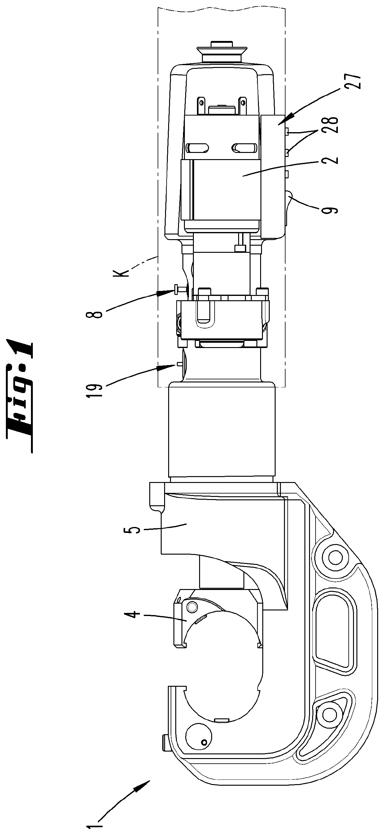
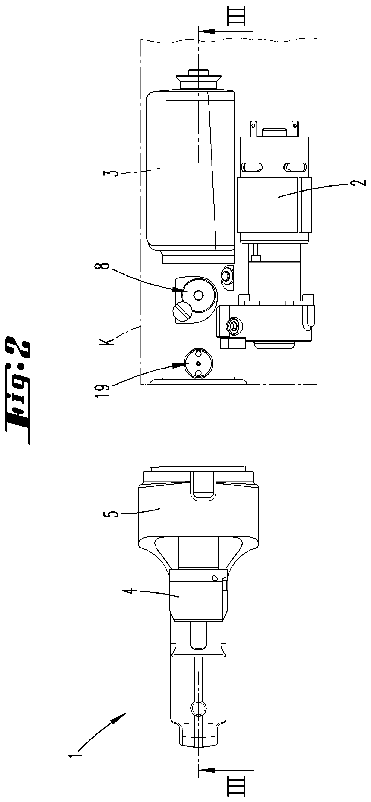
[0067]A hydraulically operated handheld device 1 in the form of a pressing device with an electric motor, 2, a not-shown hydraulic pump, a hydraulic medium reservoir 3 and a moving part 4 in the form of a hydraulic piston is initially described with reference to FIG. 1.

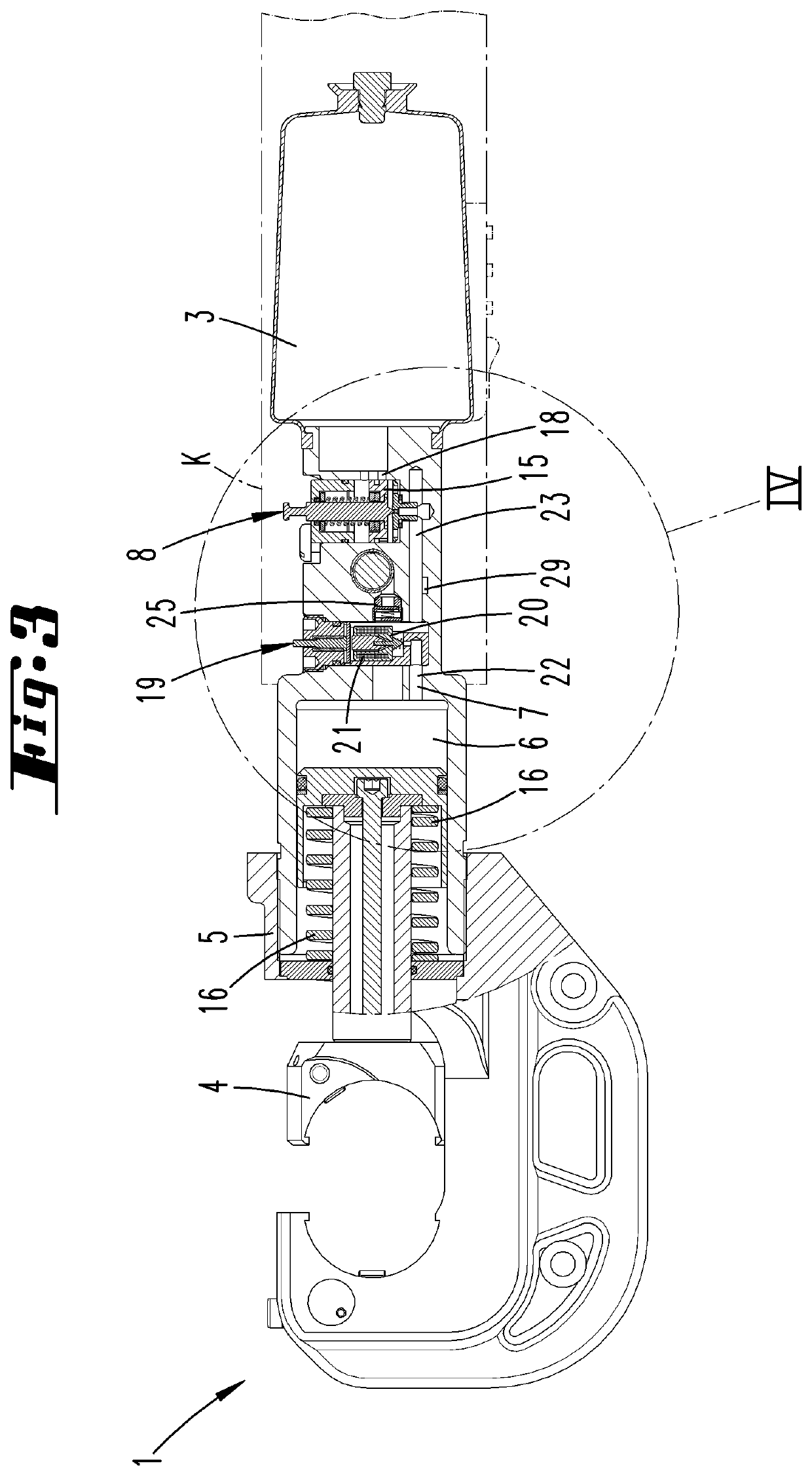
[0068]The moving part 4 can be moved relative to a fixed part 5, which is respectively formed by the device housing or, for example, the cylinder, in which the hydraulic piston moves. For example, the moving part 4 forms the tool receptacle illustrated in FIG. 1. It may also be realized, for example, in the form of a hydraulic piston (see for example FIG. 3).

[0069]Particularly the hydraulic medium reservoir 3, the return valve 8, the blocking means 19, the adjusting device 27 and, if applicable, other components are accommodated in a device body K that is not illustrated in greater detail in the figure.

[0070]The hydraulic chamber 6 comprises the space, into which hydraulic medium is pumped. This space begins on the pr...


PUM

PropertyMeasurementUnit
pressureaaaaaaaaaa
pressureaaaaaaaaaa
pressureaaaaaaaaaa

Abstract

A hydraulically operated handheld device and a method of operating same are provided. The device includes a hydraulic pump, a moving part, a fixed part and a return valve with an associated valve seat. The moving part is moved into a working position due to the buildup of a hydraulic pressure by filling a hydraulic chamber with hydraulic medium from a reservoir with the aid of the hydraulic pump. The moving part can be automatically moved back from the working position into an end position upon reaching a predefined working pressure by opening the return valve. The hydraulic pressure acting upon the return valve is increased by a separately triggerable pressure increase, which results in opening of the return valve, in a hydraulic medium volume located upstream of the return valve in a flow direction of the hydraulic medium during the movement into the end position.

Description

TECHNICAL FIELD[0001]The invention initially pertains to a method for operating a hydraulically operated handheld device, for example a pressing device and / or a hole-punching or punching device, wherein the handheld device comprises a hydraulic pump, a moving part, a fixed part and a return valve with an associated valve seat, wherein the moving part is moved into a working position due to the buildup of a hydraulic pressure, which is realized by filling a hydraulic chamber with hydraulic medium from a reservoir with the aid of the hydraulic pump, and wherein the moving part can be automatically moved back from the working position into an end position upon reaching a predefined working pressure by opening the return valve.[0002]The invention furthermore pertains to a hydraulically operated handheld device, for example a pressing device and / or a hole-punching or punching device, wherein the handheld device comprises a hydraulic pump, a moving part, a fixed part and a return valve wi...

Claims


Application Information

Patent Timeline
Patent Type & Authority Applications(United States)
IPC IPC(8): B25B27/10B21D28/34
CPCH01R43/0427B26F1/44B25B27/10B25F5/005B21D28/34B21J15/20B25B27/026B21J15/105B26F1/14
Inventor FRENKEN, EGBERT
Owner GUSTAV KLAUKE GMBH
Learn More