Liquid crystal display and manufacturing method of the same

a technology of liquid crystal display and manufacturing method, which is applied in the direction of non-linear optics, instruments, optics, etc., can solve the problems of residual image phenomenon of motion picture, difficulty in precisely controlling the initial alignment state of liquid crystal, and different alignment directions for each fine region, so as to improve the response speed of liquid crystal and simplify the rubbing method

Inactive Publication Date: 2011-10-27
SAMSUNG DISPLAY CO LTD
View PDF9 Cites 79 Cited by
  • Summary
  • Abstract
  • Description
  • Claims
  • Application Information

AI Technical Summary

Benefits of technology

[0021]According to an exemplary embodiment of the present invention, a rubbing method of the liquid crystal may be simplified, a pre-tilt of the liquid crystal may be controlled, and a response speed of the liquid crystal may be improved.

Problems solved by technology

However, since the rubbing method is mechanically performed, it is difficult to precisely control the initial alignment state of the liquid crystal and provide different alignment directions for each fine region.
Meanwhile, since the liquid crystal display changes an image through a mechanical operation of the liquid crystal, there is a problem in that a residual image phenomenon of a motion picture occurs due to a low response speed of the liquid crystal.

Method used


Image

  • Liquid crystal display and manufacturing method of the same
  • Liquid crystal display and manufacturing method of the same
  • Liquid crystal display and manufacturing method of the same

Examples


Embodiment Construction

[0059]Hereinafter, referring to the drawings, an exemplary embodiment of the present invention will be described in detail. However, the present invention is not limited to exemplary embodiments to be disclosed below and may be implemented in various forms. It will be appreciated by those skilled in the art that changes may be made in these embodiments without departing from the principles and spirit of the general inventive concept, the scope of which is defined in the appended claims and their equivalents. The same reference numerals designate the same elements throughout the specification.

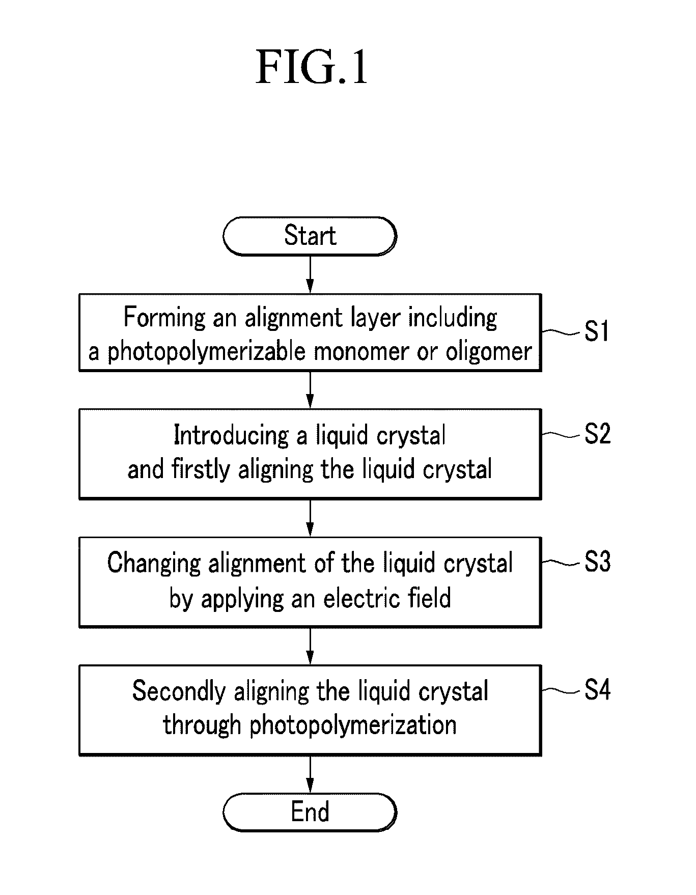
[0060]FIG. 1 is a flowchart of a method for aligning liquid crystal according to an exemplary embodiment of the present invention.

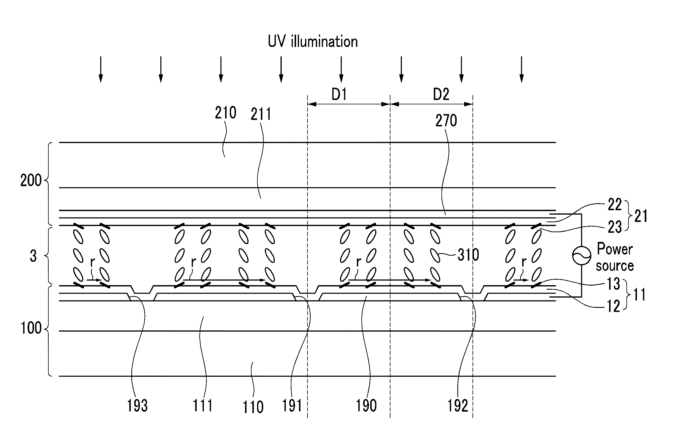
[0061]First, an alignment layer that includes a photopolymerizable monomer or oligomer is formed on a substrate or the like (S1). The photopolymerizable monomer or oligomer is mixed with the alignment base material, and is coated and cured for forming the alignment la...


PUM

PropertyMeasurementUnit
angleaaaaaaaaaa
angleaaaaaaaaaa
angleaaaaaaaaaa

Abstract

First alignment is performed by forming an alignment layer that includes a photopolymerizable monomer or oligomer on a substrate and the like, introducing liquid crystal, and bringing the liquid crystal into contact with the alignment layer including the photopolymerizable monomer or oligomer.
The liquid crystal is then subjected to secondary alignment by photopolymerizing the photopolymerizable monomer or oligomer including the alignment layer to form an alignment regulator in a state in which an electric field is applied to the liquid crystal to hange the alignment of the liquid crystal.

Description

RELATED APPLICATIONS[0001]This application claims priority of of International Patent Corporation Treaty Application No. PCT / KR2009 / 005278, filed on Sep. 17, 2009, which claims priority of Korean Patent Application No. 10-2008-0091005, filed Sep. 17, 2008, Korean Patent Application No. 10-2008-0107985, filed Oct. 31, 2008, Korean Patent Application No. 10-2008-0135660, filed Dec. 29, 2008, Korean Patent Application No. 10-2009-0000314, filed Jan. 5, 2009, Korean Patent Application No. 10-2009-0000315, filed Jan. 5, 2009, Korean Patent Application No. 10-2009-0006338, filed Jan. 23, 2009, Korean Patent Application No. 10-2009-0013929, filed Feb. 19, 2009, Korean Patent Application No. 10-2009-0013805, filed Feb. 19, 2009, Korean Patent Application No. 10-2009-0023199, filed Mar. 18, 2009, Korean Patent Application No. 10-2009-0023676, filed Mar. 19, 2009, Korean Patent Application No. 10-2009-0030068, filed Apr. 7, 2009, Korean Patent Application No. 10-2009-0042855, filed May 15, 20...

Claims


Application Information

Patent Timeline
Patent Type & Authority Applications(United States)
IPC IPC(8): G02F1/1335H01L33/16
CPCG02F1/133707G02F1/133711G02F1/133753G02F2202/023G02F2001/133715G02F2001/133726G02F2001/133742G02F1/134363G02F1/133715G02F1/133726G02F1/133742
Inventor KIM, JAE-HOON
Owner SAMSUNG DISPLAY CO LTD
Why Eureka
Try Eureka