
Illuminating Device for an Operating Microscope

Active Publication Date: 2011-10-27
LEICA MICROSYSTEMS (SCHWEIZ) AG
View PDF2 Cites 1 Cited by
  • Summary
  • Abstract
  • Description
  • Claims
  • Application Information

AI Technical Summary

Benefits of technology

[0009]The problem of the present invention is to provide an operating microscope for ophthalmic surgery with which it is easy to provide good contrast in the use of a red reflex display, e.g. for removing tissue residues from the eye.
[0018]It is also advantageously possible to provide the structure using an MMA (micromirror array), MEM (microelectromagnetic mirrors) or SLM device (spatial light modulator), particularly using OLEDs, LEDs, displays, etc. Devices of this kind allow the particularly flexible provision of structures, i.e. in a manner that can be varied to suit specific requirements.
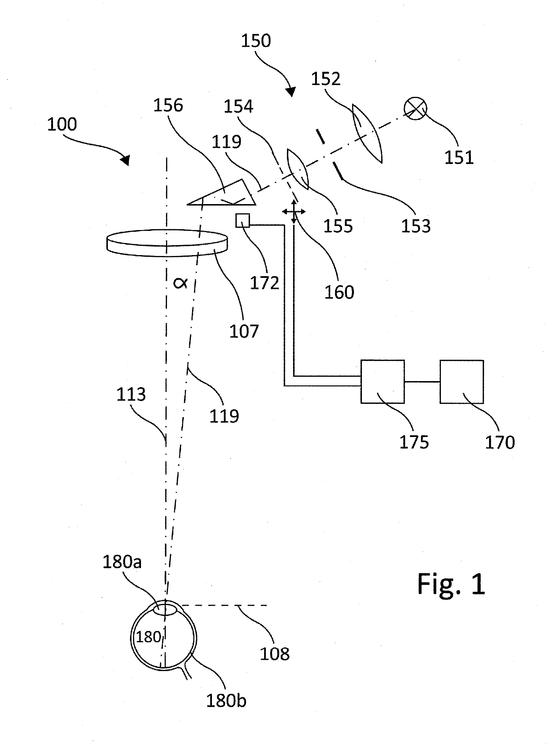
[0021]It has proved advantageous to make the illuminating device capable of being switched on and off, the deflector in particular being capable of being taken out of the observation beam path altogether. This makes it possible in particular to provide an unobstructed additional illumination of the object or eye that is to be observed, in which the illuminating device according to the invention is totally removed from the observation beam paths.
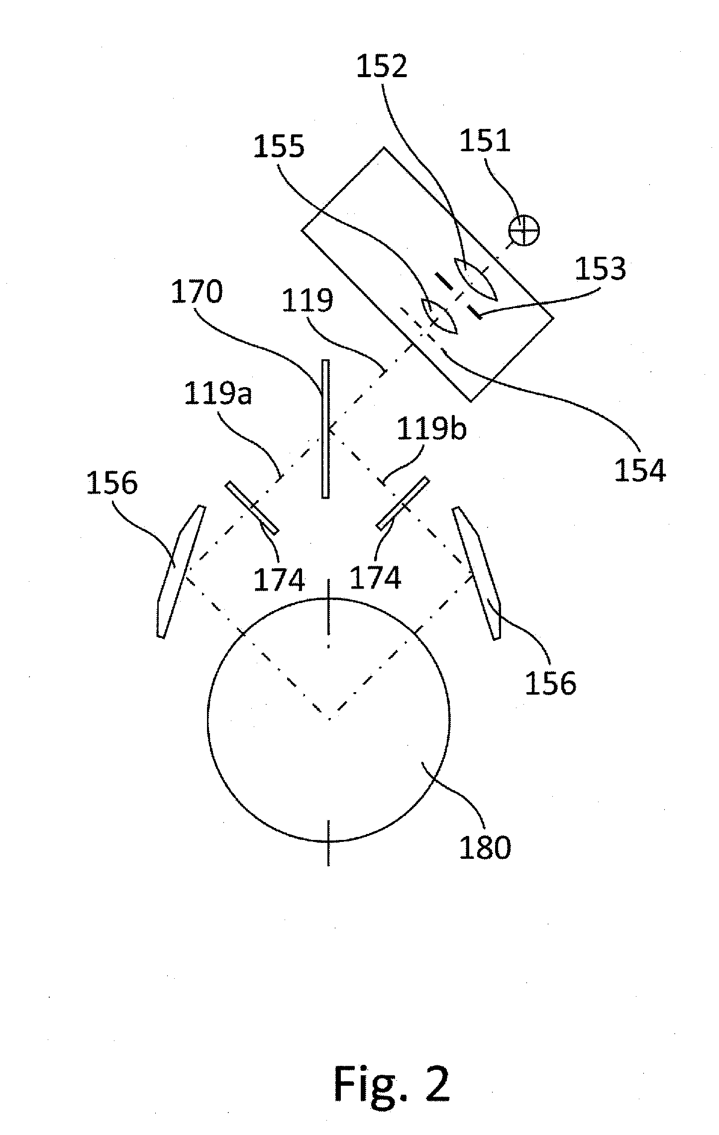
[0022]According to another particularly preferred embodiment, the illuminating device according to the invention comprises a beam splitter for splitting the illumination beam path into two partial beam paths, each partial beam path having an associated deflector. This measure makes it possible to provide simultaneous illumination from different angles, also known as stereoscopic illumination, each of the partial beam paths being acted upon by the structure having transparent and non-transparent regions. As a result, overlapping or interfering patterns can be displayed on the retina, thus enabling variable patterns to be produced on the retina using only a device for acting upon the illumination beam path with one structure, by slightly varying the deflection angles of the deflectors, and / or the orientation of the beam splitter, for example.

Problems solved by technology

This also takes account of the fact that eyes under examination have physiological differences from one another, so that precise imaging on the retina may be a very tricky process.

Method used


Image

  • Illuminating Device for an Operating Microscope
  • Illuminating Device for an Operating Microscope
  • Illuminating Device for an Operating Microscope

Examples


Embodiment Construction

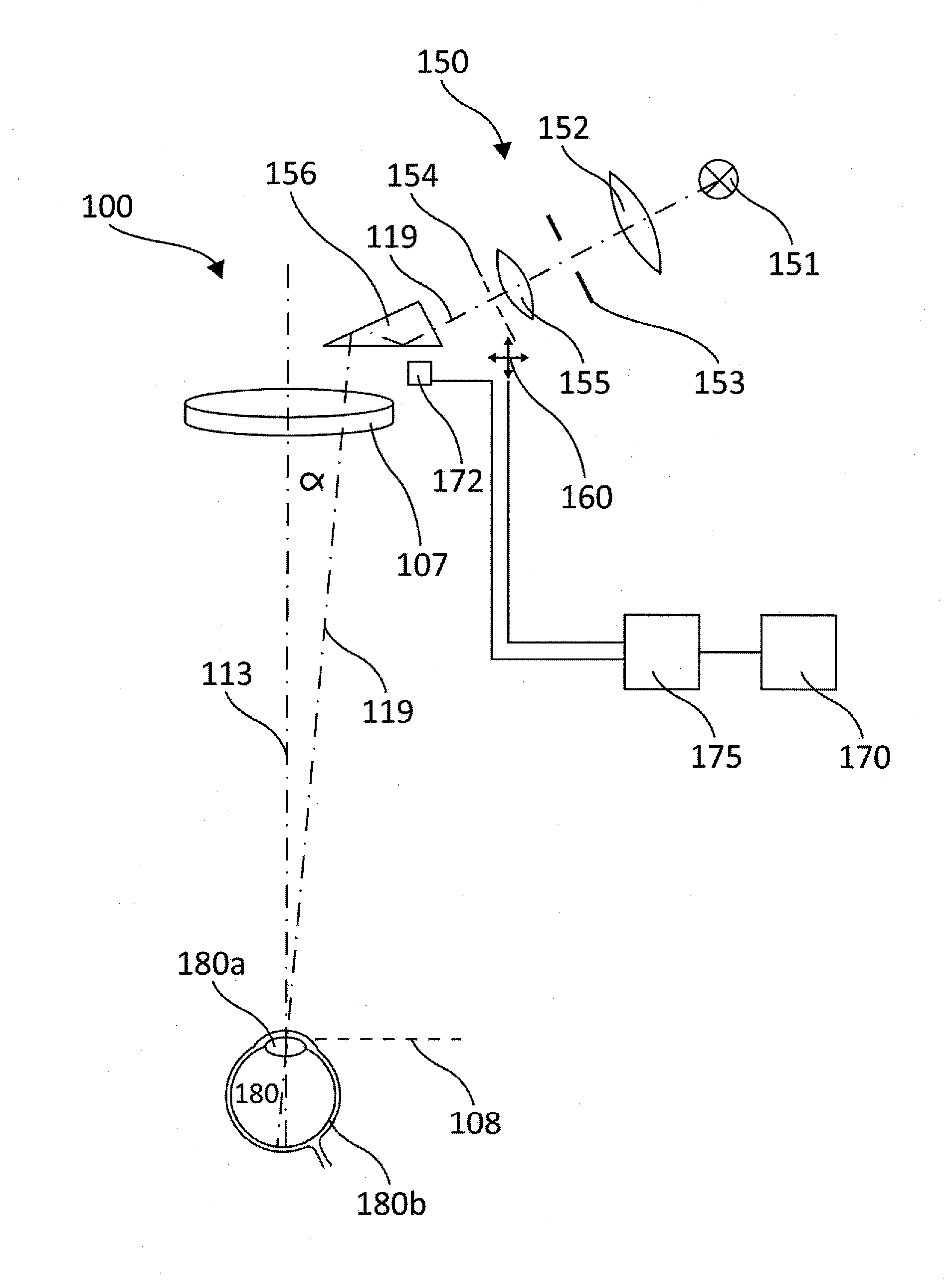
[0030]A microscope that comprises a first preferred embodiment of the illuminating device according to the invention is shown purely schematically in FIG. 1 and generally designated 100. The only optical component of the microscope specifically shown is the main objective 107. An illuminating device is generally designated 150. It comprises a light source 151, a collector lens system 152, a luminous field diaphragm (aperture) 153, other lenses shown schematically and designated 155 and a deflecting prism 156 serving as a deflector. An additional element is a further diaphragm (aperture) 154 provided between the luminous field diaphragm 153 and the deflecting prism 156. This diaphragm 154 for the purposes of the present invention represents a device for acting upon an observation beam path with a structure, and is explained in detail hereinafter.

[0031]An illumination beam path 119 is passed from the light source 151 through the collector lens system 152, the luminous field diaphragm ...


PUM


Abstract

The present invention relates to an Illuminating device for an operating microscope in ophthalmic surgery, having at least one light source (151), at least one lens (152, 155), at least one luminous field diaphragm (153), and at least one optical deflector (156), wherein in order to provide an illumination beam path (119) light from the light source (151) is guided through a main objective (107) which is disposed between the deflector (156) and an eye (180) that is to be observed, and on to the eye that is to be observed, wherein a device (154) that can be introduced into the illumination beam path (119) for acting upon the illumination beam path (119) with a structure that comprises transparent and non-transparent or opaque regions such that this structure can be imaged on or close to the retina (180b) of the eye (180) that is to be observed.

Description

CROSS-REFERENCE TO RELATED APPLICATIONS[0001]This application claims priority to German Patent Application No. DE 10 2010 028 169.7 filed on Apr. 23, 2010, that is incorporated herein by reference in its entirety.FIELD OF THE INVENTION[0002]The present invention relates to an illuminating device for an operating microscope, particularly in ophthalmic surgery, according to the preamble of claim 1.BACKGROUND OF THE INVENTION[0003]When operating microscopes are used in eye surgery, particularly in cataract removal, the angle between the illumination axis and the observation axis of the microscope should be kept as small as possible. The advantage of this type of illumination is that the rays of light falling perpendicularly onto the eye are reflected diffusely by the retina and as a result the lens capsule of the eye appears as a translucent reddish colour. This effect is also known as the red reflex. The quality of this red reflex is of critical importance in cataract removal. In this...

Claims


Application Information

Patent Timeline
IPC IPC(8): A61B3/135
CPCA61B3/13A61B19/5202G02B21/06G02B21/0012A61B19/5223A61B90/20A61B90/30
Inventor SANDER, ULRICH
Owner LEICA MICROSYSTEMS (SCHWEIZ) AG
Learn More