

Photographing optical lens assembly
a technology of optical lenses and lens assemblies, applied in the field of photography optical lens assemblies, can solve the problems of difficult manufacturing process for bonding glass lenses, limited freedom of optical system design, and difficult shortening of the total track length of the system, so as to reduce the total track length of the lens assembly, reduce the sensitivity of the optical system, and improve the resolution image quality
- Summary
- Abstract
- Description
- Claims
- Application Information
AI Technical Summary
Benefits of technology
Problems solved by technology
Method used
Image

Examples
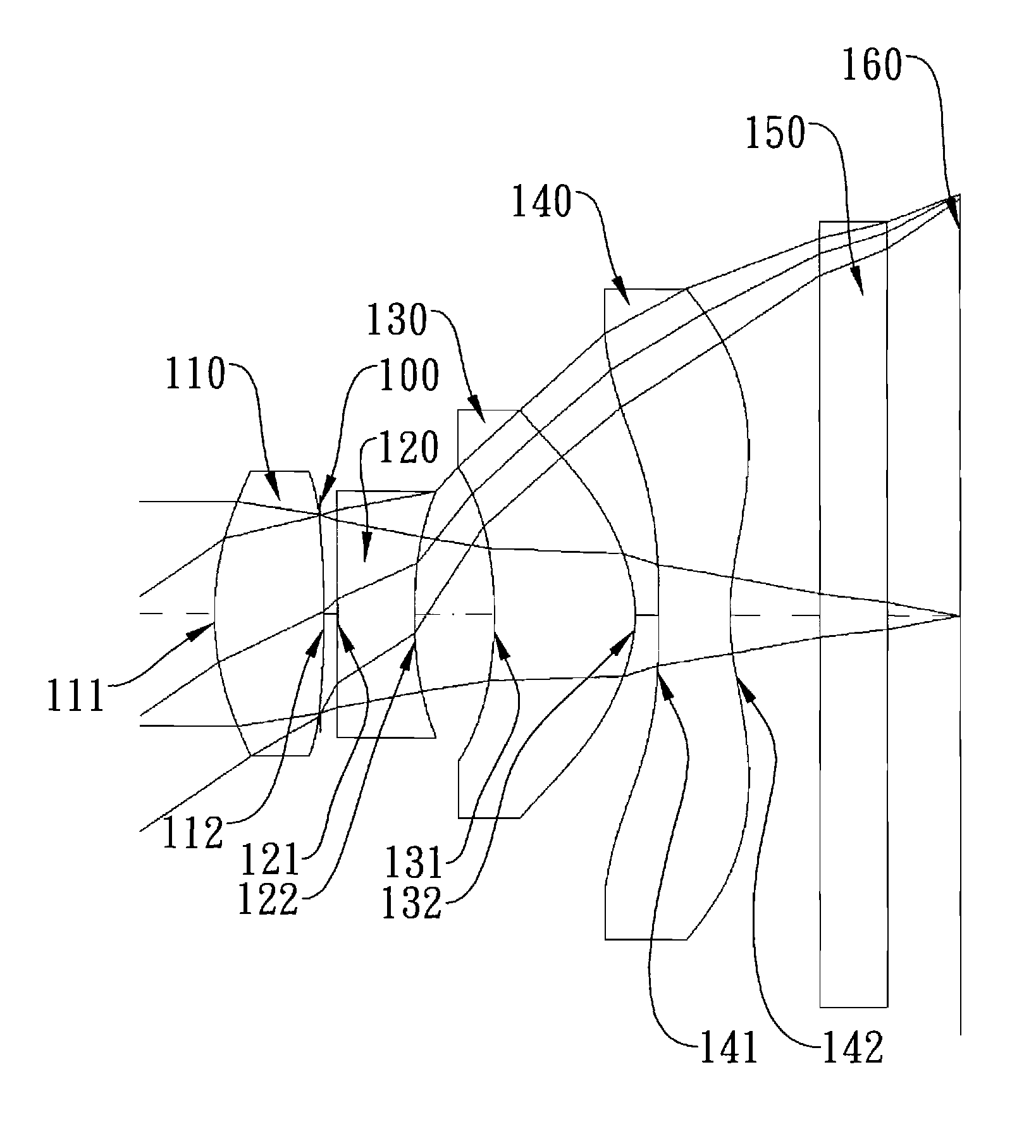
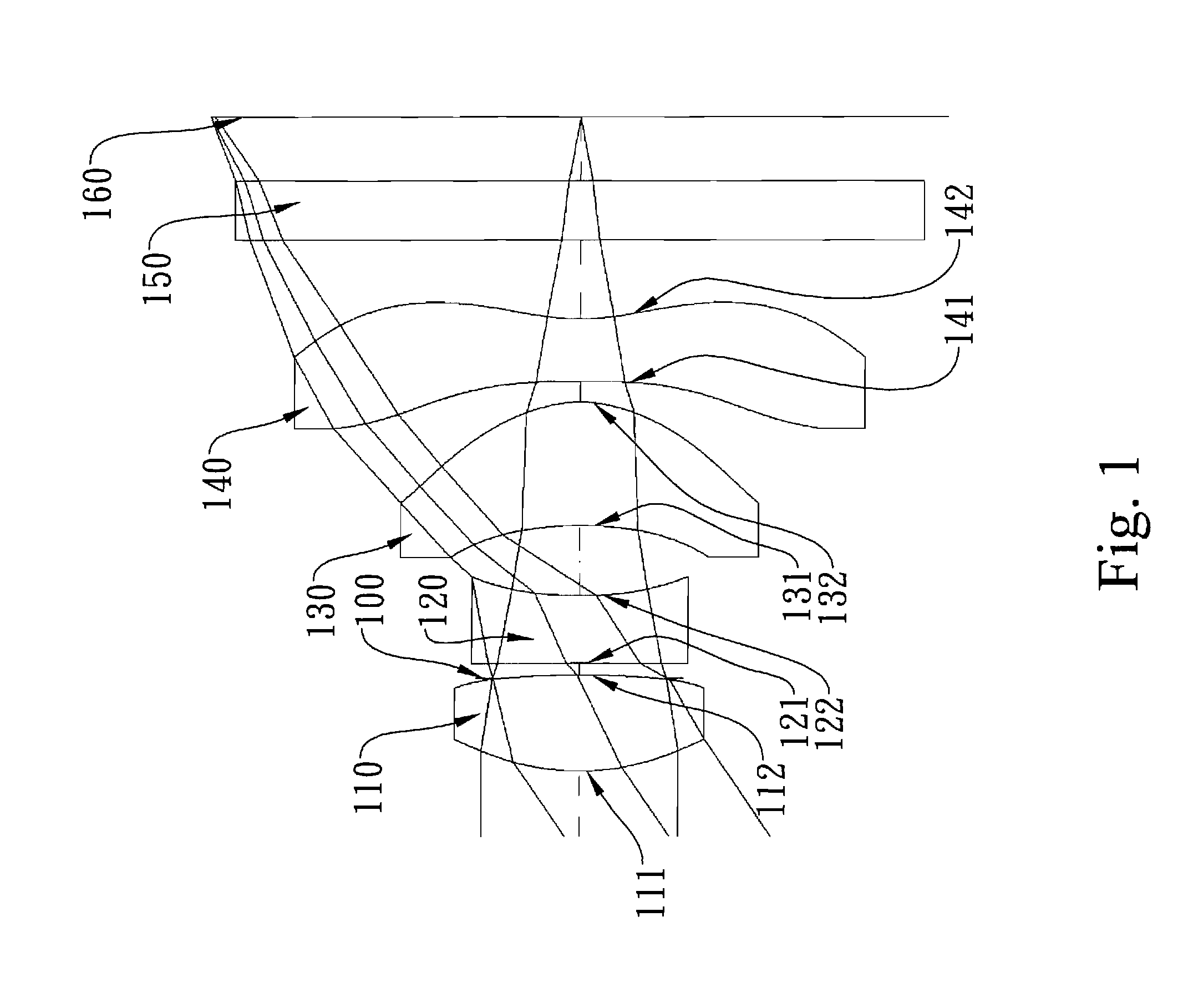
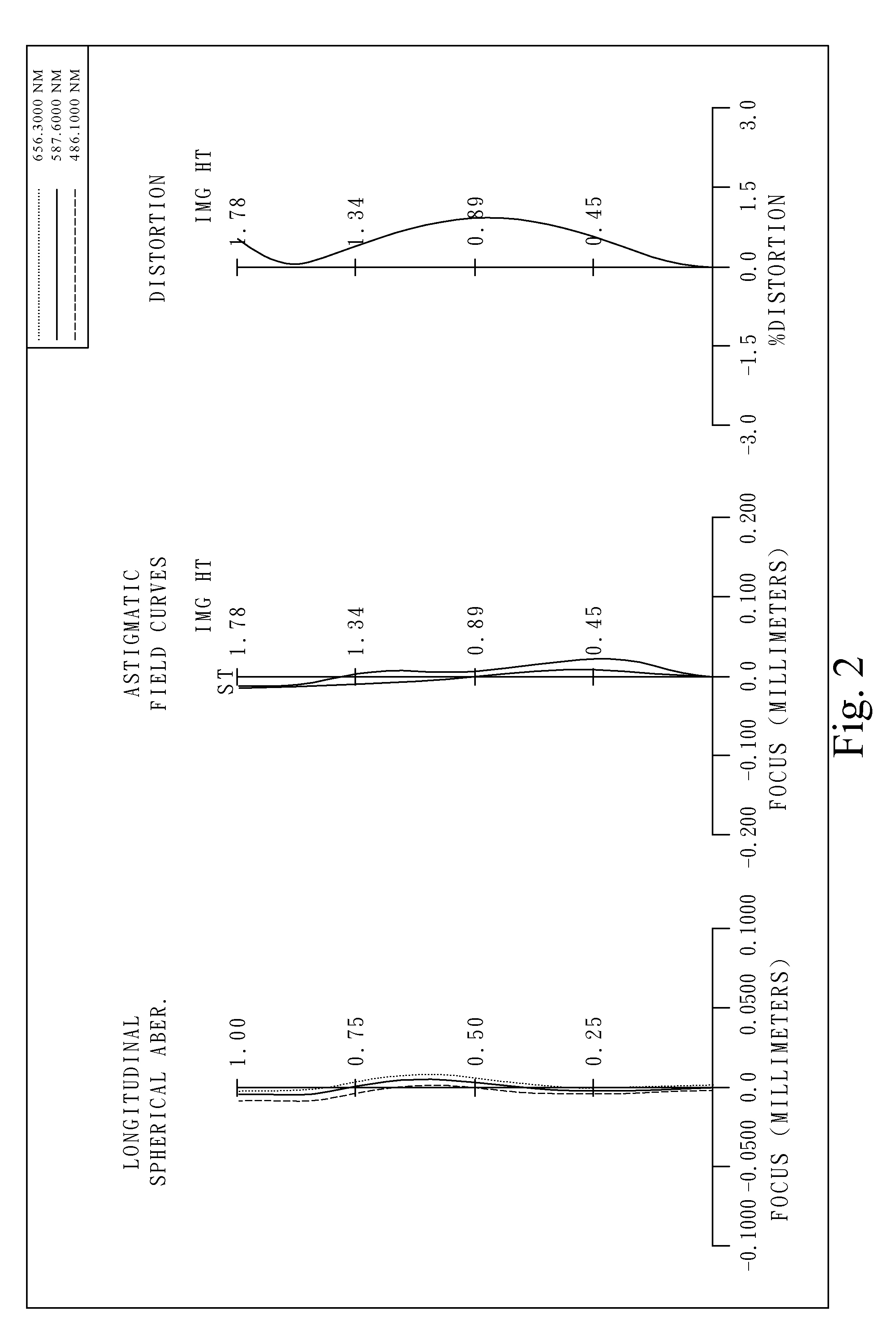
first embodiment
[0076]In the present photographing optical lens assembly, the focal length of the photographing optical lens assembly is f, and it satisfies the relation:
f=2.72 (mm).
[0077]In the first embodiment of the present photographing optical lens assembly, the f-number of the photographing optical lens assembly is Fno, and it satisfies the relation:
Fno=2.85.
[0078]In the first embodiment of the present photographing optical lens assembly, half of the maximal field of view of the photographing optical lens assembly is HFOV, and it satisfies the relation:
HFOV=33.1 deg.
[0079]In the first embodiment of the present photographing optical lens assembly, the Abbe number of the first lens element 110 is V1, the Abbe number of the second lens element 120 is V2, and they satisfy the relation:
V1−V2=32.5.
[0080]In the first embodiment of the present photographing optical lens assembly, the distance on the optical axis between the first lens element 110 and the second lens element 120 is T12, the focal leng...
second embodiment
[0094]In the present photographing optical lens assembly, the focal length of the photographing optical lens assembly is f, and it satisfies the relation:
f=4.57 (mm).
[0095]In the second embodiment of the present photographing optical lens assembly, the f-number of the photographing optical lens assembly is Fno, and it satisfies the relation:
Fno=2.85.
[0096]In the second embodiment of the present photographing optical lens assembly, half of the maximal field of view of the photographing optical lens assembly is HFOV, and it satisfies the relation:
HFOV=31.8 deg.
[0097]In the second embodiment of the present photographing optical lens assembly, the Abbe number of the first lens element 310 is V1, the Abbe number of the second lens element 320 is V2, and they satisfy the relation:
V1−V2=32.5.
[0098]In the second embodiment of the present photographing optical lens assembly, the distance on the optical axis between the first lens element 310 and the second lens element 320 is T12, the focal ...
third embodiment
[0112]In the present photographing optical lens assembly, the focal length of the photographing optical lens assembly is f, and it satisfies the relation:
f=3.76 (mm).
[0113]In the third embodiment of the present photographing optical lens assembly, the f-number of the photographing optical lens assembly is Fno, and it satisfies the relation:
Fno=2.50.
[0114]In the third embodiment of the present photographing optical lens assembly, half of the maximal field of view of the photographing optical lens assembly is HFOV, and it satisfies the relation:
HFOV=30.6 deg.
[0115]In the third embodiment of the present photographing optical lens assembly, the Abbe number of the first lens element 510 is V1, the Abbe number of the second lens element 520 is V2, and they satisfy the relation:
V1−V2=32.5.
[0116]In the third embodiment of the present photographing optical lens assembly, the distance on the optical axis between the first lens element 510 and the second lens element 520 is T12, the focal leng...
PUM
 Abstract
Description
Claims
Application Information