Press-fit busbar and busway employing same

a busbar and press-fit technology, applied in the direction of single bars/rods/wires/strips conductors, coupling device connections, conductors, etc., can solve the problems of shape, flexibility and size limitations inherent in such designs, and achieve enhanced electrical contact, high current capacity, and improved manufacturability

Active Publication Date: 2011-10-27
UNIVERSAL ELECTRIC
View PDF5 Cites 30 Cited by
  • Summary
  • Abstract
  • Description
  • Claims
  • Application Information

AI Technical Summary

Benefits of technology

[0012]The present invention solves the problems described above and satisfies the need for an increased current-capacity compression busbar that provides contact pressure by means of a flexible conductive system. The invention provides an improved electrical power distribution system that permits continuous access for inserting take-off devices and also has high current capacity. The invention provides enhanced electrical contact between the busbars and the stabs on take-off devices. It provides firm contact pressure and large contact surface area and allows a take-off device to be inserted at any point along the track. It further provides improvements in manufacturability of a higher-current carrying busbar by virtue of an inventive construction.

Problems solved by technology

The current-carrying capacity of such design is limited to the thickness of the copper and therefore to the shape, flexibility and size limitations inherent to copper of that thickness.

Method used


Image

  • Press-fit busbar and busway employing same
  • Press-fit busbar and busway employing same
  • Press-fit busbar and busway employing same

Examples


Embodiment Construction

[0048]Directional phrases used herein, such as, for example, left, right, front, back, top, bottom and derivatives thereof, relate to the orientation of the elements shown in the drawings and are not limiting upon the claims unless expressly recited therein. Identical parts are provided with the same reference number in all drawings.

[0049]As employed herein, the term “number” shall be used to refer to any non-zero quantity (i.e. one or any quantity greater than one).

[0050]As employed herein, the statement that two or more parts are “coupled” together shall mean that the parts are joined together either directly or joined through one or more intermediate parts.

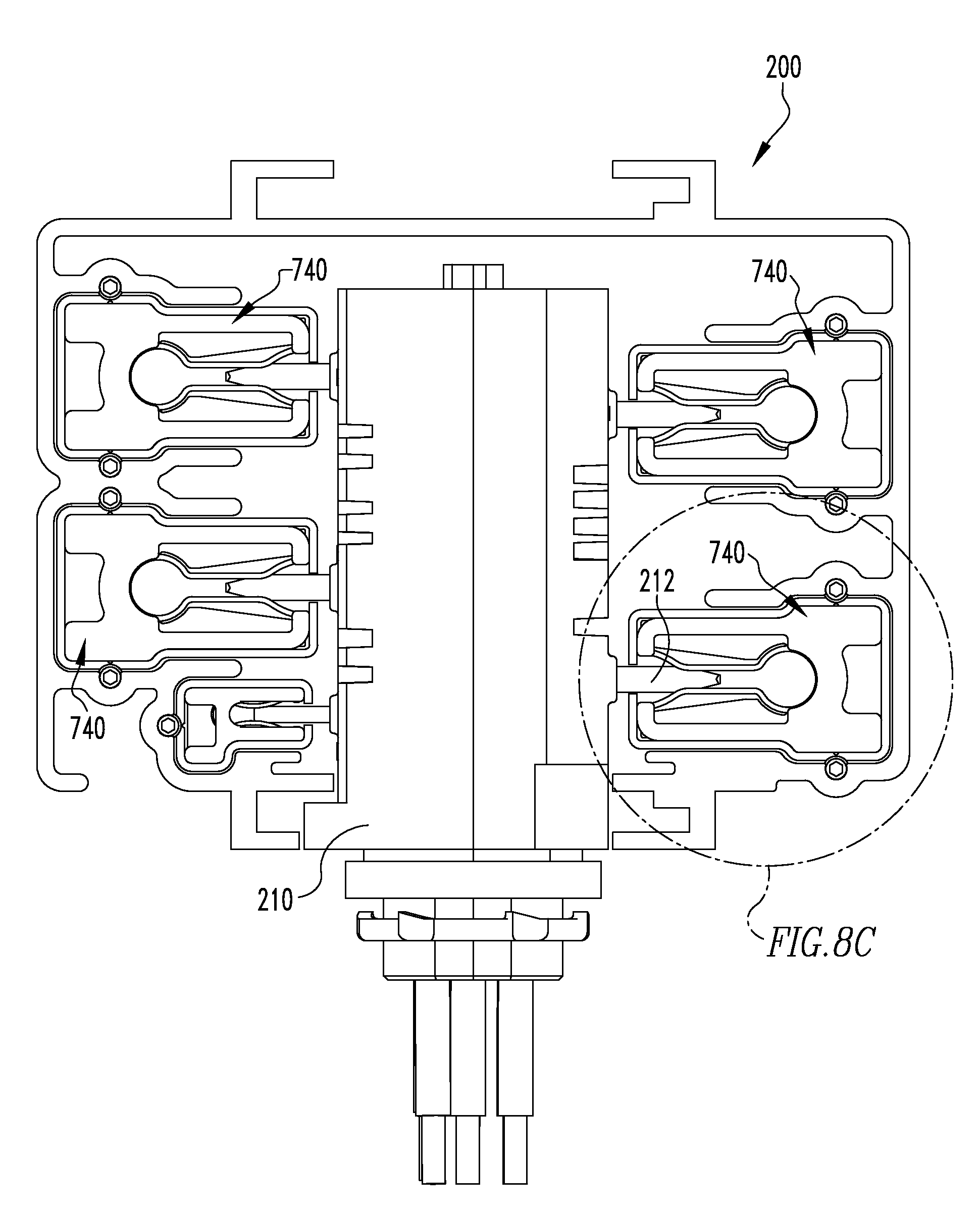
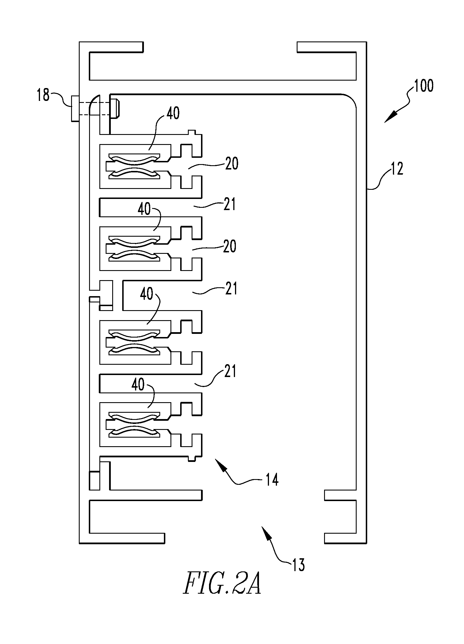
[0051]The present invention is directed to an improved electrical power distribution system that provides continuous access for inserting take-off devices and also high current capacity. The invention provides enhanced electrical contact between the busbars and the stabs on take-off devices. The invention provides firm contact ...


PUM

PropertyMeasurementUnit
thicknessaaaaaaaaaa
thicknessaaaaaaaaaa
lengthaaaaaaaaaa

Abstract

An improved conductive busbar assembly and power distribution track utilizing the improved conductive busbar assembly. The busbar assembly including an inner component adapted to engage a stab member of a plug-in unit and an outer component disposed about, and in contact with, the inner component. The inner and outer components are both formed from an electrically conductive material. The busbar assembly provides greater current-carrying capacity and permits take-off devices to be installed at any point along the busway run.

Description

CLAIM TO PRIORITY[0001]This application claims priority to U.S. provisional application No. 61 / 326,878 filed Apr. 22, 2010, entitled “Improved Press-Fit Busbar and Busway Employing Same”, the contents of which are incorporated herein by reference.BACKGROUND[0002]1. Field of the Invention[0003]The present invention relates to an electrical distribution track in which multiple electrically-isolated, conductive busbars are housed in an elongated enclosure for feeding higher-current electricity to take-off devices that may be inserted into the track at any point along the length of the track to make electrical contact with the busbars.[0004]2. Background Information[0005]It is common in factories, shops, offices and other buildings to install overhead electrical power distribution tracks for providing a convenient source of electricity for lights, machines and other electrical devices in the buildings.[0006]Electrical power distribution tracks are typically comprised of an elongated hou...

Claims


Application Information

Patent Timeline
Patent Type & Authority Applications(United States)
IPC IPC(8): H02B1/32H02B1/20
CPCH01B13/34H01B5/02Y10T29/49117H01R25/14H01R25/16H02G5/00
Inventor ROSS, STEVEN L.GRIFFITH, RUSSELL C.
Owner UNIVERSAL ELECTRIC
Why Eureka
Try Eureka