Knuckle protector for a vehicle

a technology for protecting knuckles and vehicles, applied in the direction of shafts, cables, vehicles/pulleys, etc., can solve the problems of long process, high cost, handling and stamping tooling, etc., and achieve the effect of simple fabrication, less cost, and resistance to deformation

Inactive Publication Date: 2011-10-27
A RAYMOND & CO
View PDF13 Cites 5 Cited by
  • Summary
  • Abstract
  • Description
  • Claims
  • Application Information

AI Technical Summary

Benefits of technology

[0010]The present invention provides a device for protecting the knuckle joint of a vehicle that is simple to fabricate and less costly, and is resistant to deformation in order not to damage the nearby steering and suspension elements.
[0012]This arrangement contributes to obtaining a protection device that can be fabricated mainly by bending sheet metal, because the length of the connecting zone between screen and flange is not excessive. It is clear that this notch in the form of a slot, separating the side wing from the flange, leads to the creation of a large protection surface with a sufficiently small connecting zone in order to form the device by bending. Contrary to a deep draw stamping operation, bending is a simple, inexpensive and fast operation, which can be performed by a conventional machine tool.
[0013]On the other hand, satisfactory resistance to deformation of the screen with one or two side wings, for instance under the influence of vehicle vibrations, is obtained very simply by means of a blocking feature which is easy to fabricate by cutting and bending the sheet metal at each side wing and flange.

Problems solved by technology

The process is not only long but also costly in energy, handling and stamping tooling.

Method used


Image

  • Knuckle protector for a vehicle
  • Knuckle protector for a vehicle
  • Knuckle protector for a vehicle

Examples


Embodiment Construction

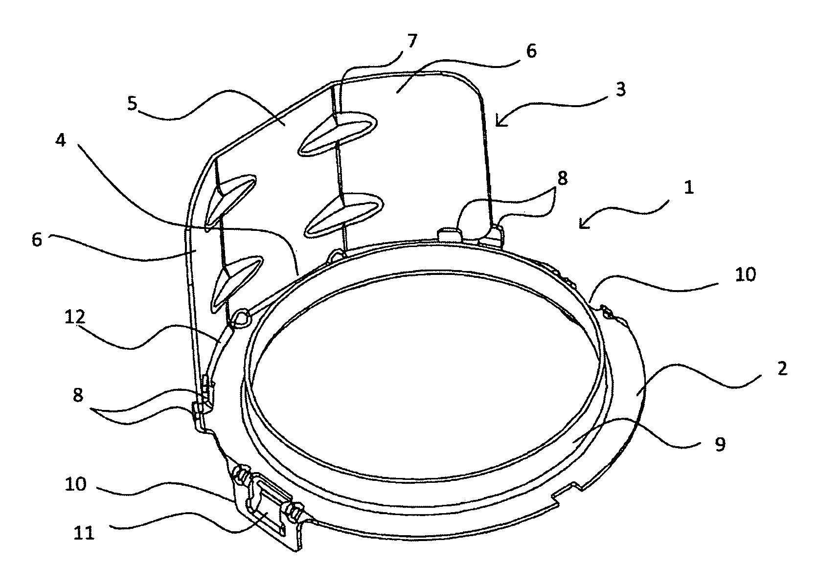
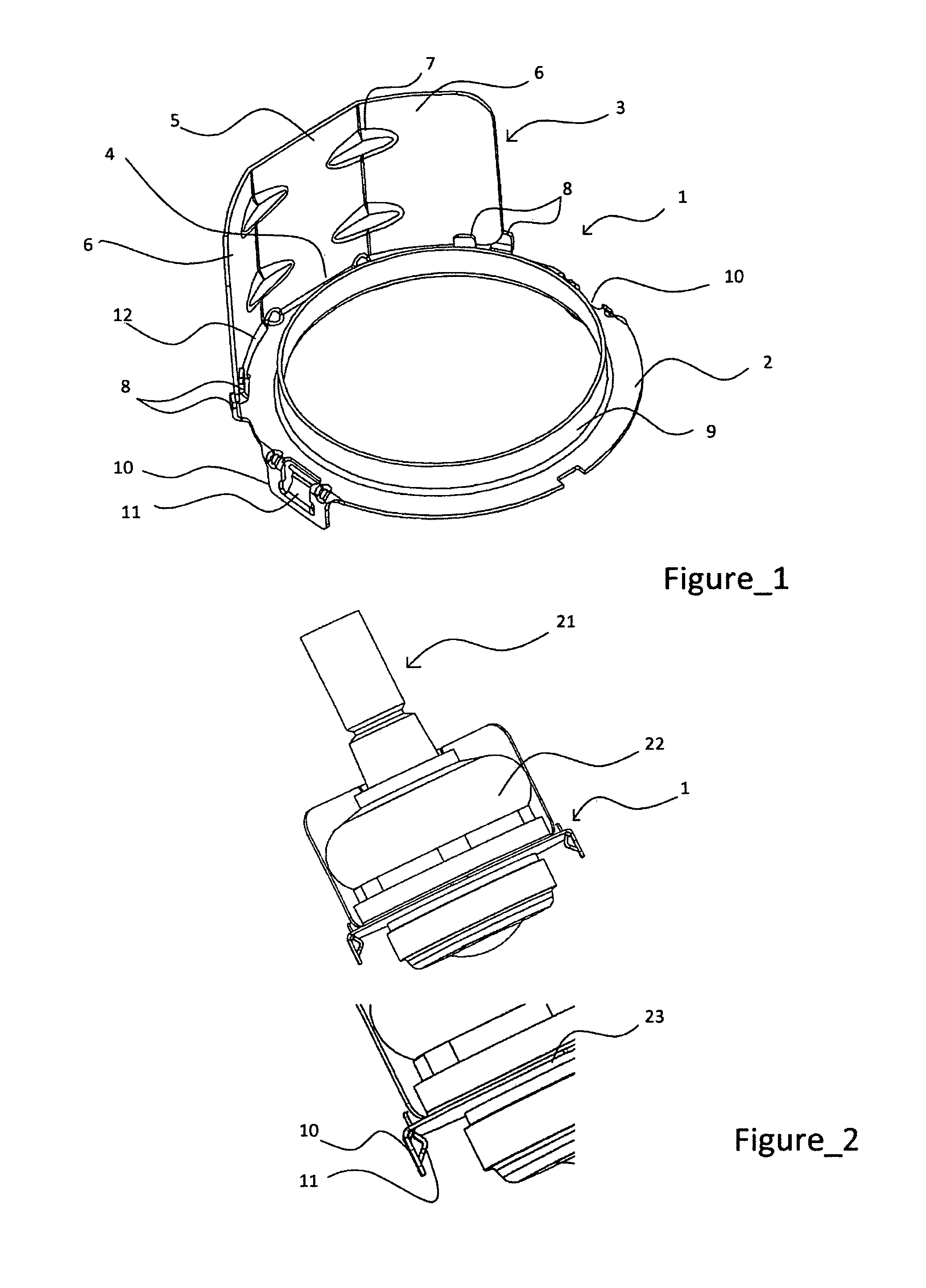
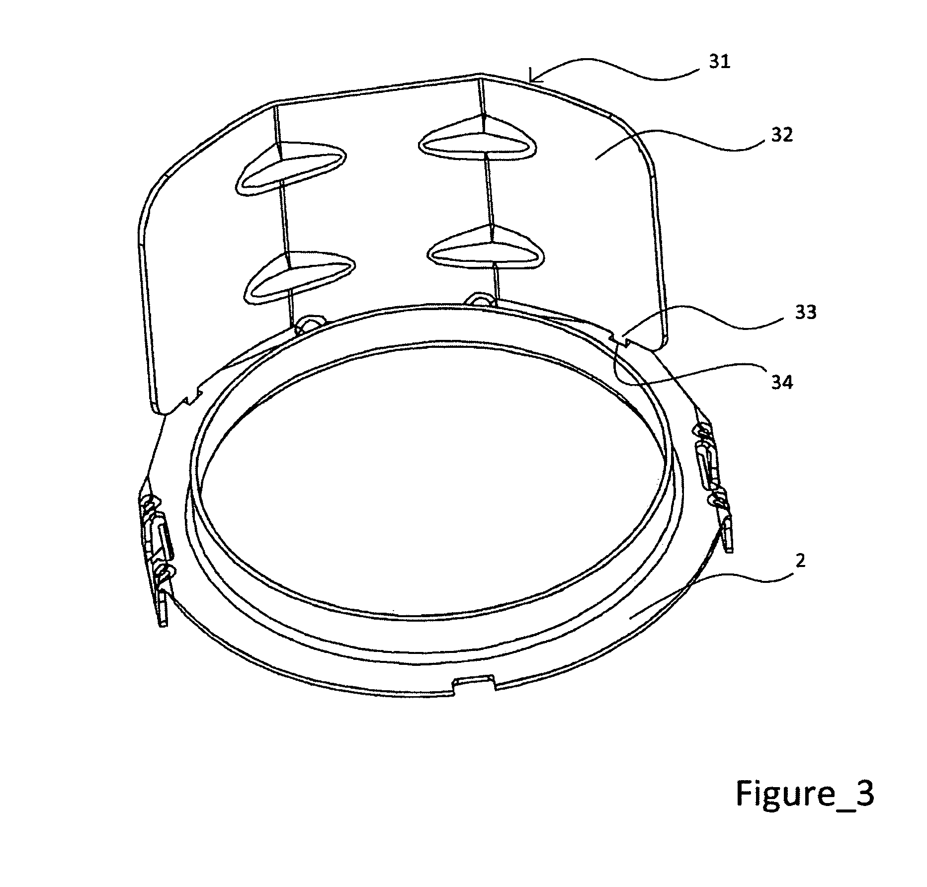
[0027]FIG. 1 shows a protection device 1 for knuckle joint (illustrated in FIG. 2) of a vehicle comprising mainly an annular flange 2 mounted on the knuckle joint, here in the form of a disc with a central opening, and a heat screen 3 for protecting against the heat emitted by the brake discs. Screen 3 extends in height perpendicularly to flange 2 and in width along the annular periphery of the flange.

[0028]The central opening of the mounting flange 2 has a circular shape mating with the also circular external contour of the knuckle, over which it passes for installation of the protection device. For instance, the inside diameter of the opening measures 44 m and the external diameter of the annular flange 2 measures 55 mm.

[0029]The heat screen has a rectangular shape and its dimensions are sufficient to protect the whole surface of the rubber boot of the knuckle, deflecting the heat effects and creating an air zone. For instance, the size of the screen can be 57 mm wide and 28 mm hi...


PUM


Abstract

The invention relates to a protection device (1) for a knuckle joint (21) e.g. for the steering and / or suspension of a vehicle, which comprises an annular flange (2) for securing a thermal screen (3) to the knuckle joint, said screen extending lengthwise substantially perpendicular to the flange (2) and widthwise substantially along the, annular periphery of the flange. The screen and the flange are formed as a single part in a metal sheet that is folded in a linking area between the screen and the flange, the screen further including a surface portion in the form of a side tab (6) extending along the annular periphery of the flange, said side tab being separated from the flange by a notch (12) in the metal sheet, in the form of a slot.

Description

CROSS-REFERENCE TO RELATED APPLICATION[0001]This application is a U.S. National Phase Patent Application based on International Application Serial No. PCT / EP2009 / 006172 filed Aug. 26, 2009, the disclosure of which is hereby explicitly incorporated by reference herein.BACKGROUND OF THE INVENTION[0002]1. Field of the Invention[0003]The present invention relates to a device for protecting a knuckle joint, which is for instance an element of the front steering or the suspension of a vehicle.[0004]In the domain of automotive engineering, this type of knuckle joint, also called knuckle, is mounted on the ball joint pin of the suspension arm or on the ball joint pin of the steering rack. In both cases, the knuckle is very close to the brake disc, which is a significant heat source. For instance, the brake disc of a loaded utility vehicle can reach a temperature of up to 700° C.[0005]A knuckle comprises mainly a knuckle articulation which is crimped to create the articulation and a boot in ...

Claims


Application Information

Patent Timeline
Patent Type & Authority Applications(United States)
IPC IPC(8): F16D1/00
CPCB60G7/005B60G2204/416B60G2204/4308Y10T403/17F16C11/0666Y10T403/16Y10T403/32852B62D7/166F16C11/06F16C2202/24F16C11/0619F16C11/0671F16C17/243F16C2326/24F16C2326/05
Inventor GARCIA, FLORENT
Owner A RAYMOND & CO
Why Eureka
Try Eureka