Wire saw and method for fabricating the same

a wire saw and wire saw technology, applied in the field of wire saws, can solve the problems of low processing efficiency, quality and precision degraded, environmental pollution and waste of abrasives,

Inactive Publication Date: 2011-10-27
KINIK
View PDF15 Cites 42 Cited by
  • Summary
  • Abstract
  • Description
  • Claims
  • Application Information

AI Technical Summary

Problems solved by technology

However, the free abrasive wire saw slicing process has drawbacks of environmental pollution and waste of abrasives and low processing efficiency.
However, the aggregation of abrasives easily occurs in the plating process, and thereby it is necessary to control the dispersion and concentration of the abrasives in the plating bath to prevent the cutting quality and precision from being degraded by the aggregation of abrasives.
Thereby, the cutting quality and precision of wire saws manufactured by the processes described in those patent documents also may be degraded due to the aggregation of abrasives.
Moreover, regarding the wire saws disclosed by JP 2007203393 and JP 2007268627, the abrasives are exposed and thereby may be separated from the core wire during the slicing process, resulting in the reduction of cutting efficiency and tool lifetime.
However, the photocurable resin layer 14 cannot provide sufficient strength to firmly hold the abrasives 12, and the abrasives 12 are partially exposed.
Thereby, the abrasives 12 may be separated from the core wire during the slicing process, resulting in the reduction of cutting efficiency.

Method used


Image

  • Wire saw and method for fabricating the same
  • Wire saw and method for fabricating the same
  • Wire saw and method for fabricating the same

Examples


example 1

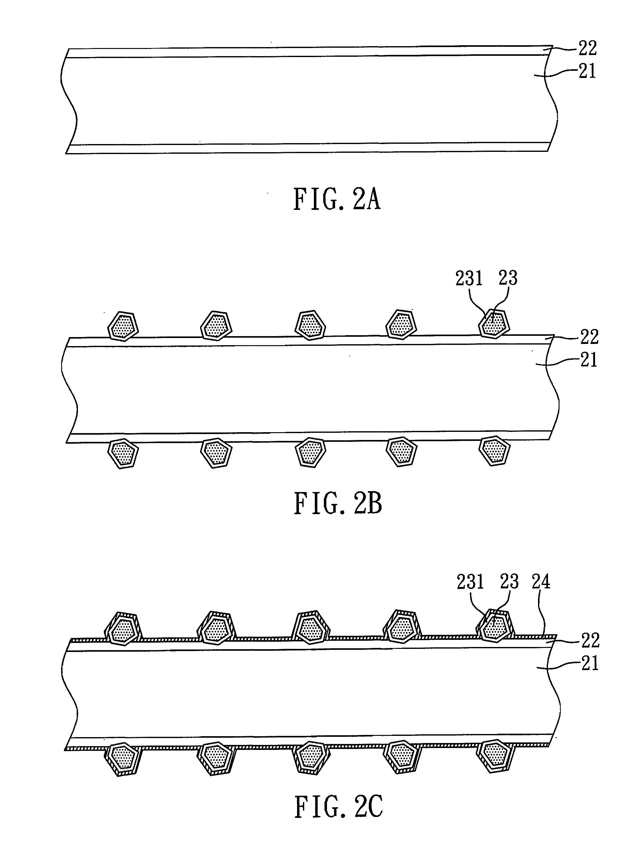
[0023]FIGS. 2A to 2C show a process for fabricating a wire saw according to the present example.

[0024]As shown in FIG. 2A, a core wire 21 is first provided, and an intermediate layer 22 is coated on the core wire 21. In the present example, the core wire 21 is a piano wire, and the intermediate layer 22 is a water layer. Subsequently, as shown in FIG. 2B, plural abrasives 23 are embedded into the intermediate layer 22. In the present example, the abrasives 23 are diamond particles coated with a conductive layer 231, and the conductive layer 231 is made of titanium.

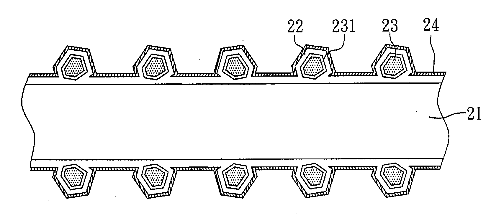
[0025]Finally, as shown in FIG. 2C, a metal protective layer 24 (i.e. an electroplating layer) is formed by electroplating to cover the abrasives 23 and the intermediate layer 22. In the present example, the metal protective layer 24 is made of nickel.

[0026]According to the above-mentioned process, the present example provides a wire saw, as shown in FIG. 2G, which includes: a core wire 21; an intermediate layer 22, dispos...

example 2

[0027]The manufacturing process according to the present example is almost the same as that of Example 1, as shown in FIGS. 2A to 2C, except that the intermediate layer 22 of the present example is an electroplating solution layer, and the conductive layer 231 is made of nickel.

example 3

[0028]The manufacturing process according to the present example is almost the same as that of Example 1, as shown in FIG. 3, except that the intermediate layer 22 of the present example is formed on the core wire 21 by mixing a resin (as a component of the intermediate layer) with the abrasives 23 to form a mixture and then coating the mixture on the core wire 21. Accordingly, the abrasives 23 are embedded in and covered by the intermediate layer 22. In addition, the metal protective layer 24 of the present example is formed by a chemical plating process (i.e. an electroless plating process) and thus is called a chemical plating layer.


PUM

PropertyMeasurementUnit
adhesiveaaaaaaaaaa
abrasivesaaaaaaaaaa
conductiveaaaaaaaaaa

Abstract

The present invention relates to a wire saw and a method for fabricating the same. The method for fabricating a wire saw according to the present invention includes: providing a core wire; coating an intermediate layer over the core wire, and embedding a plurality of abrasives in the intermediate layer; and plating a metal protective layer over the abrasives. Accordingly, the present invention can resolve the conventional problem of abrasives in the plating bath aggregating during electroplating deposition, so as to enhance cutting quality and precision.

Description

CROSS REFERENCE TO RELATED APPLICATION[0001]This application claims the benefits of the Taiwan Patent Application Serial Number 099113262, filed on Apr. 27, 2010, the subject matter of which is incorporated herein by reference.BACKGROUND OF THE INVENTION[0002]1. Field of the Invention[0003]The present invention relates to a wire saw and a method for fabricating the same, more particularly, to wire saw advantageous to the enhancement of cutting quality and having an extended lifetime and a method for fabricating the same.[0004]2. Description of Related Art[0005]Wire-saw cutting is a processing method for cutting semiconductors, crystals, various single crystals, magnetic materials, ceramic materials and other hard-brittle materials. Wire saws with free abrasives have been widely applied in a process for cutting semiconductor wafers, which use steel wire and free abrasives dispersed in a liquid to remove materials. However, the free abrasive wire saw slicing process has drawbacks of e...

Claims


Application Information

Patent Timeline
Patent Type & Authority Applications(United States)
IPC IPC(8): B23D61/18B24D3/00B24D11/00
CPCB23D61/185B23D65/00B24D18/0018B24D3/34B24B27/0633
Inventor LIU, YEN-KANGLEE, YI-TSANGKAO, CHIEN-WEI
Owner KINIK
Why Eureka
Try Eureka