
Method For Slicing A Multiplicity Of Wafers From A Workpiece

a technology of multiplicity and workpiece, applied in the direction of metal sawing devices, metal sawing accessories, manufacturing tools, etc., can solve the problems of increased wire wear, different degree of wear of sawing wire, and disadvantageous table forward feed

Active Publication Date: 2008-06-19
SILTRONIC AG
View PDF6 Cites 28 Cited by
  • Summary
  • Abstract
  • Description
  • Claims
  • Application Information

AI Technical Summary

Benefits of technology

The invention is a method for slicing wafers from a workpiece using a wire saw. The method aims to achieve uniform wear of the sawing wire over its length while avoiding the drawbacks of previous methods. This is achieved by regulating the effective speed of the sawing wire based on the forward feed rate and the workpiece's cross section, resulting in uniform wear of the sawing wire.

Problems solved by technology

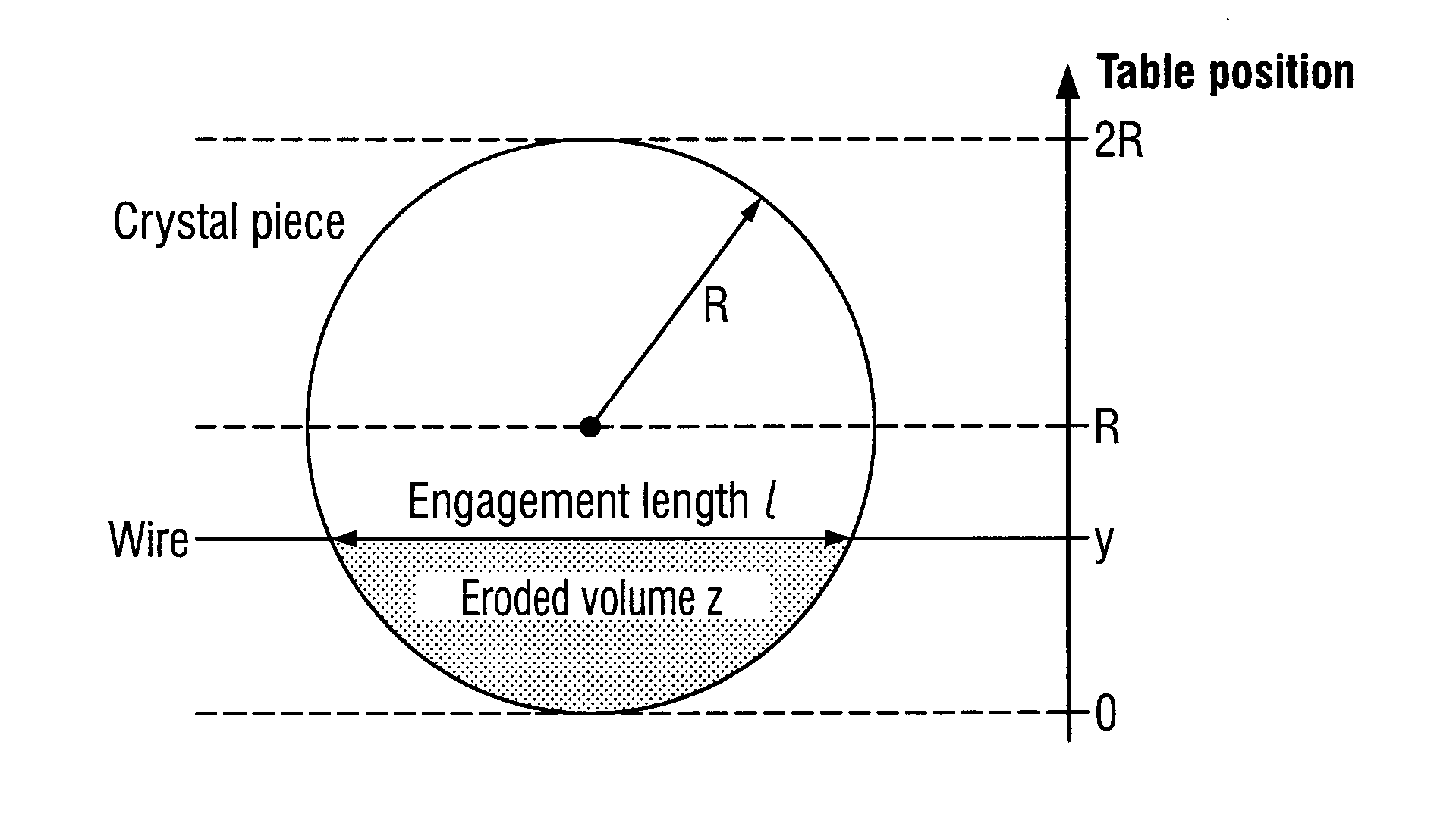
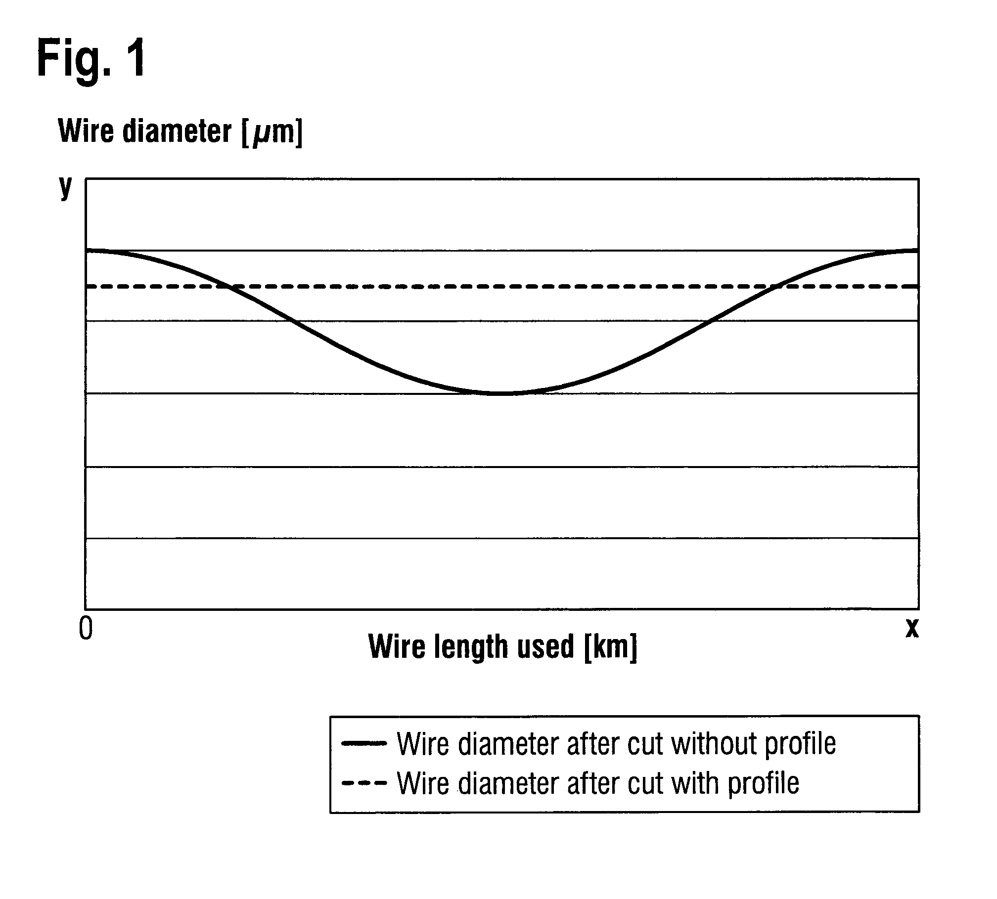
In the prior art, the problem arises during wire sawing that the sawing wire experiences a different degree of wear as a function of the incision length.
When slicing semiconductor wafers with sizeable diameters from a crystal, for example 300 mm wafers, a table forward feed being kept constant is however disadvantageous since the total thickness variance (TTV) of the semiconductor wafers is thereby increased in the region of the greatest incision lengths.
A constant table forward feed, as disclosed in U.S. Pat. No. 6,109,253 A, is therefore undesirable.
At the start of the cutting process, this leads to initially increased wire wear which is subsequently reduced by lowering the table forward feed.

Method used


Image

  • Method For Slicing A Multiplicity Of Wafers From A Workpiece
  • Method For Slicing A Multiplicity Of Wafers From A Workpiece
  • Method For Slicing A Multiplicity Of Wafers From A Workpiece

Examples


example

[0049]A crystal piece having a diameter of 150 mm was fastened on a sawing beam having a width of 70 mm (cf. also FIG. 4).

[0050]The table forward feed profile was specified according to Table 1 (linear interpolation was carried out between the support points, cf. also FIG. 5).

TABLE 1Table position (mm)Table forward feed rate (μm / min)0600106002036075240130360155360

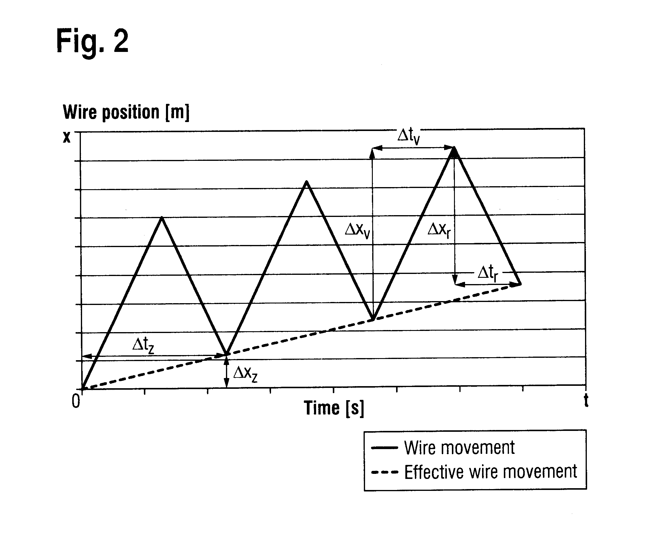
[0051]For this cutting, 20 km of wire were available, the wire speed was at most 12 m / s and the acceleration when reversing direction was 3 m / s2. The optimized wire movements represented in FIG. 6 were produced by the wire program represented in Table 2, with the assumption that the wire wear is proportional to the eroded volume and the requirement that 30 cycles should be executed per 10 mm of forward feed.

TABLE 2Wire movementWire movementforward per cyclebackward per cycleTable position (mm)(m)(m)0132132113612851411231014412015192162202692353029125240315271603723247542737790372324110315271120291252130269235135267237140264...


PUM

PropertyMeasurementUnit
speedaaaaaaaaaa
incision lengthaaaaaaaaaa
lengthaaaaaaaaaa

Abstract

A multiplicity of wafers are sliced from a workpiece which has a longitudinal axis and a cross section, the workpiece fastened on a table being fed by a relative movement directed perpendicularly to the longitudinal axis of the workpiece between the table and the wire gang of a wire saw, with a variable forward feed rate through the wire gang formed by a sawing wire moved with an effective speed, the effective speed of the sawing wire being regulated as a function of the forward feed rate and the workpiece cross section so as to result in uniform wear of the sawing wire.

Description

BACKGROUND OF THE INVENTION[0001]1. Field of the Invention[0002]The invention relates to a method for slicing a multiplicity of wafers from a workpiece by means of a wire saw.[0003]2. Background Art[0004]Wire saws are suitable, for example, for slicing a multiplicity of semiconductor wafers, solar wafers and other crystal wafers from a crystal piece in one working step. The functional principle of such a wire saw is described in U.S. Pat. No. 5,771,876. Wire saws have a wire gang, which is formed by a sawing wire that is wound around two or more wire feed or guide rolls. The sawing wire may be covered with a cutting layer. When using wire saws having a sawing wire without firmly bound cutting abrasive, cutting abrasive in the form of a suspension (slurry) is supplied during the slicing process.[0005]During the slicing process, the workpiece fastened on a table passes through the wire gang, in which the sawing wire is arranged in the form of wire sections lying parallel to one anothe...

Claims


Application Information

Patent Timeline
Patent Type & Authority Applications(United States)
IPC IPC(8): B28D1/02
CPCB23D57/0046B28D5/045B23D59/001B23D57/0053H01L21/30
Inventor SKOVGAARD-SOERENSEN, FRANKMAHNKE, MATTHIASKASINGER, THOMAS
Owner SILTRONIC AG
Learn More