
Apparatus and Method for Frequency-Selective Occupancy Detection

a technology of frequency-selective occupancy and apparatus, applied in electrical apparatus, network traffic/resource management, transmission monitoring, etc., can solve the problems of significant changes in the power spectral density of parts, measurement errors, and the change of the receive spectrum, so as to achieve a well-scalable

Active Publication Date: 2011-10-27
INNOVATIONSZENTRUM FUER TELEKOMMUNIKATIONSTECHNIK GMBH IZT
View PDF7 Cites 10 Cited by
  • Summary
  • Abstract
  • Description
  • Claims
  • Application Information

AI Technical Summary

Benefits of technology

[0029]Embodiments of the present invention comprise the following advantages or the presented method is particularly effective in the following features:
[0032]Further, elimination of static signals to a large extent can be obtained with as good an approximation of the noise floor as possible.

Problems solved by technology

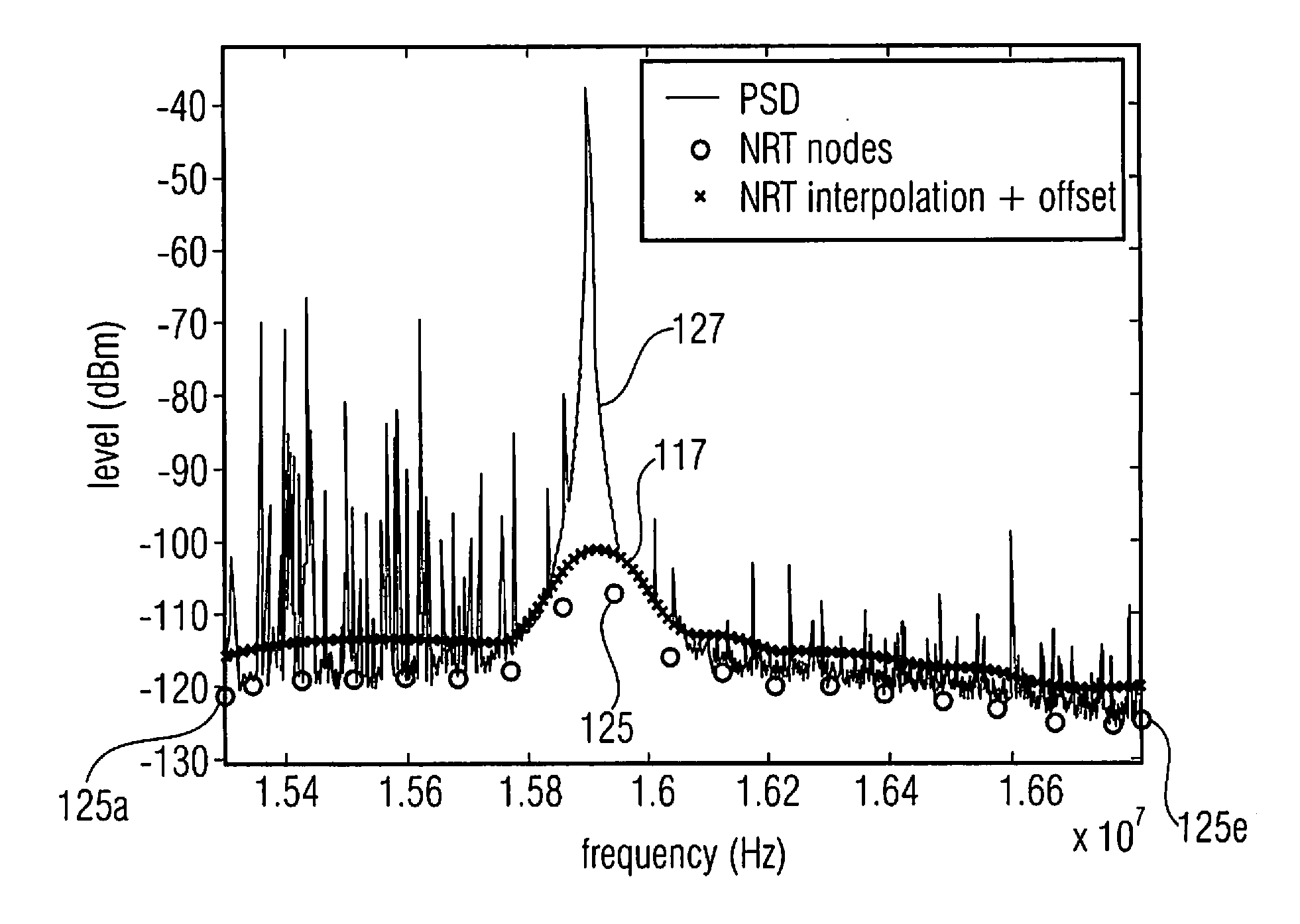
The disadvantage of this method is that the receive spectrum (power spectral density=PSD) changes significantly in parts when the receiver (e.g. the antenna, bandwidth, etc.) changes.
However, it is a disadvantage of this method that in real situations, due to the structure of the receiver, receive spectra are to be measured which are not flat but, for example, arranged in a rising manner towards higher frequencies or also in a falling manner.
In this case, the radio channels are classified as active or inactive, depending on their position in the receive spectrum, which results in measurement errors.

Method used


Image

  • Apparatus and Method for Frequency-Selective Occupancy Detection
  • Apparatus and Method for Frequency-Selective Occupancy Detection
  • Apparatus and Method for Frequency-Selective Occupancy Detection

Examples


Embodiment Construction

[0046]Regarding the following description, it should be noted that in the different embodiments, the same or equal functional elements have the same reference numbers and hence the description of these functional elements in the different embodiments illustrated below are interchangeable.

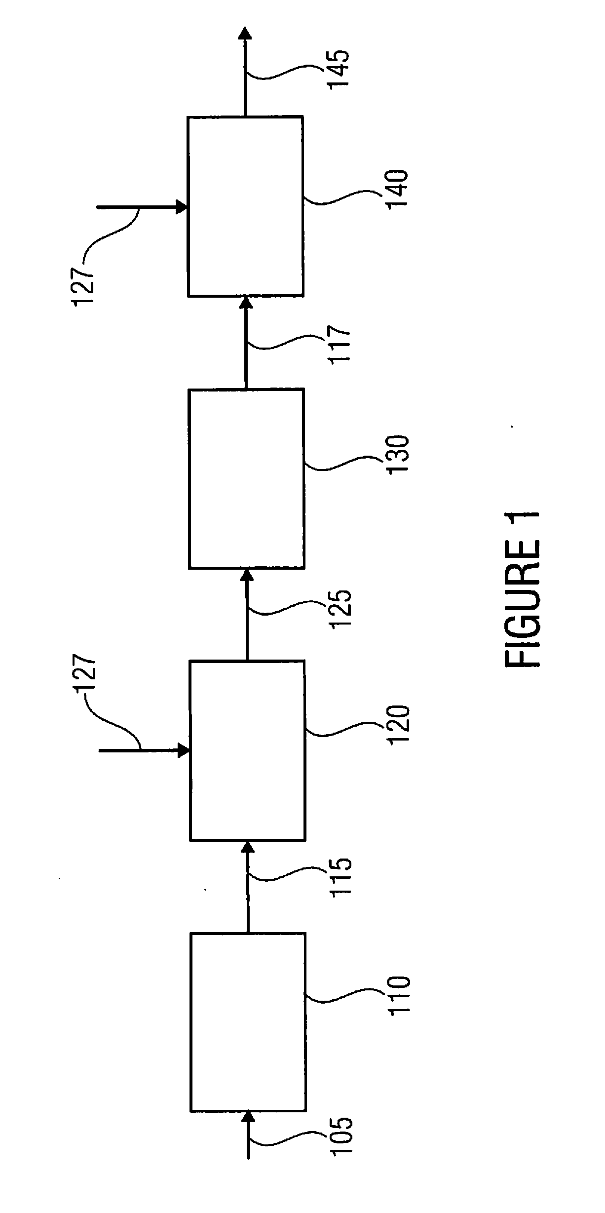
[0047]FIG. 1 shows a schematic illustration of an embodiment of the present invention. The apparatus for frequency-selective occupancy detection of a channel in a frequency band comprises a means 105 for detecting a receive spectrum in the frequency band, a means 110 for providing node frequencies 115, a means 120 for determining node level values 125, a means 130 for determining the threshold curve 117 and a means 140 for comparing.

[0048]The inventive apparatus serves for frequency-selective occupancy detection of a channel in a frequency band, wherein first a receive spectrum is detected by a means 105 (e.g. an input) and supplied to means 110. Means 110 provides the node frequencies 115 for a thr...


PUM


Abstract

An apparatus for frequency-selective occupancy detection of a channel in a frequency band includes a detector for detecting a receive spectrum in the frequency band, a provider for providing node frequencies, a determiner for determining node level values, a determiner for determining the threshold curve and a comparer. The provider provides the node frequencies for a threshold curve with respect to a noise floor in the frequency band. The determiner determines the node level values at the node frequencies based on receive level values of the receive spectrum. The determiner determines the threshold curve in the frequency band based on the provided node frequencies and the node level values at the node frequencies. The comparer compares a current power of the receive level values in the channel with a reference power in the channel predetermined by the threshold curve to detect occupancy or non-occupancy of the channel depending on the comparison.

Description

CROSS-REFERENCE TO RELATED APPLICATIONS[0001]This application is a continuation of copending International Application No. PCT / EP2009 / 007417, filed Oct. 15, 2009, which is incorporated herein by reference in its entirety, and additionally claims priority from German Application No. DE 10 2008 054 070.6, filed Oct. 31, 2008, which is incorporated herein by reference in its entirety.BACKGROUND OF THE INVENTION[0002]The present invention relates to an apparatus and method for detecting occupancy of a channel within a frequency band, and in particular to a frequency-selective occupancy measurement based on a threshold determined from the noise floor.[0003]In order to be able to perform frequency-selective spectrum occupancy measurement of radio channels, for example, exact determination of a threshold is necessitated, above the value of which the channel to be measured is classified as currently active, or below which the channel is classified as currently inactive.[0004]Further, by fre...

Claims


Application Information

Patent Timeline
Patent Type & Authority Applications(United States)
IPC IPC(8): H04W24/00
CPCH04W16/14H04W24/00H04B17/382H04W72/042H04B17/318H04W28/04H04W72/23
Inventor PERTHOLD, RAINERWENINGER, DIETERSCHLEGEL, HOLGER
Owner INNOVATIONSZENTRUM FUER TELEKOMMUNIKATIONSTECHNIK GMBH IZT
Learn More