Reconfigurable Navigated Surgical Tool Tracker

a surgical tool and navigation system technology, applied in the field of reconfigurable navigated surgical tool trackers, can solve the problems of tracking problems, system cannot locate, and inaccurate tool location data from the navigation system

Inactive Publication Date: 2011-10-27
BLUE BELT TECH
View PDF7 Cites 77 Cited by
  • Summary
  • Abstract
  • Description
  • Claims
  • Application Information

AI Technical Summary

Benefits of technology

[0016]These and other features and characteristics of the present invention, as well as the methods of operation and functions of the related elements of structures and combinations of parts and economies of manufacture, will become more apparent upon consideration of the following description and the appended claims with reference to the accompanying drawings, all of which form a part of this specification, wherein like reference numerals designate corresponding parts in the various figs. It is to be expressly understood, however, that the drawings are for the purpose of illustration and description only and are not intended to unduly limit the present invention. As used in the specification and the claims, the singular form of “a”, “an”, and “the” include plural referents unless the context clearly dictates otherwise.

Problems solved by technology

These tracker frames may be large relative to the tracked objects and anatomy they are used to track and may cause interference with one another.
This creates problems during surgery if the tracked tool and / or objects are not detected and may require repositioning where the tracker is not visible to the camera.
If the tool somehow moves relative to the tracker (e.g., when the tracker mount loosens and the tracker frame shifts relative to the tool), the tool location data from the navigation system is no longer accurate.
This could create a problem in a variety of surgeries using navigation in that the presence of a tracker and / or navigation instrumentation may prohibit motion of the tool beyond what is “allowed” in the presence of the tracker frame.
Such a restriction could create a physical barrier (e.g., when the tracker frame hits something that keeps the surgeon from moving the tracked tool to the proper orientation), or it could create a tracking problem when the tracker frame is blocked from (camera's) view (e.g., when the tool cutting guard prevents a particular cut and the tool must be rotated out of the field of view) and the system cannot locate the tracked tool even when the tool itself may be oriented in an ideal (desired) position according to the surgeon.
If the tracker frame is rigidly attached to the top of the tool and visible only in an upright position, then when the tool is flipped 180 degrees, the tracker may no longer be visible to the camera and the tracking may be interrupted, making navigation-based completion of the surgical procedure nearly impossible.
Hence, real time tracking of the tool would be interrupted, despite surgically correct (and desirable) location of the tool.
However, in various applications, such additional tracker may not be desirable or practical.
For example, in a surgical bone-cutting procedure, the additional tracker may become cumbersome, add weight, reduce ergonomics, and prohibit gripping of the tool in certain orientations that are required to properly cut the bone.

Method used


Image

  • Reconfigurable Navigated Surgical Tool Tracker
  • Reconfigurable Navigated Surgical Tool Tracker
  • Reconfigurable Navigated Surgical Tool Tracker

Examples


Embodiment Construction

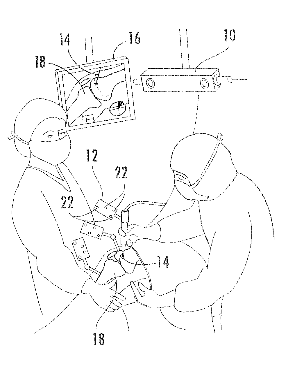
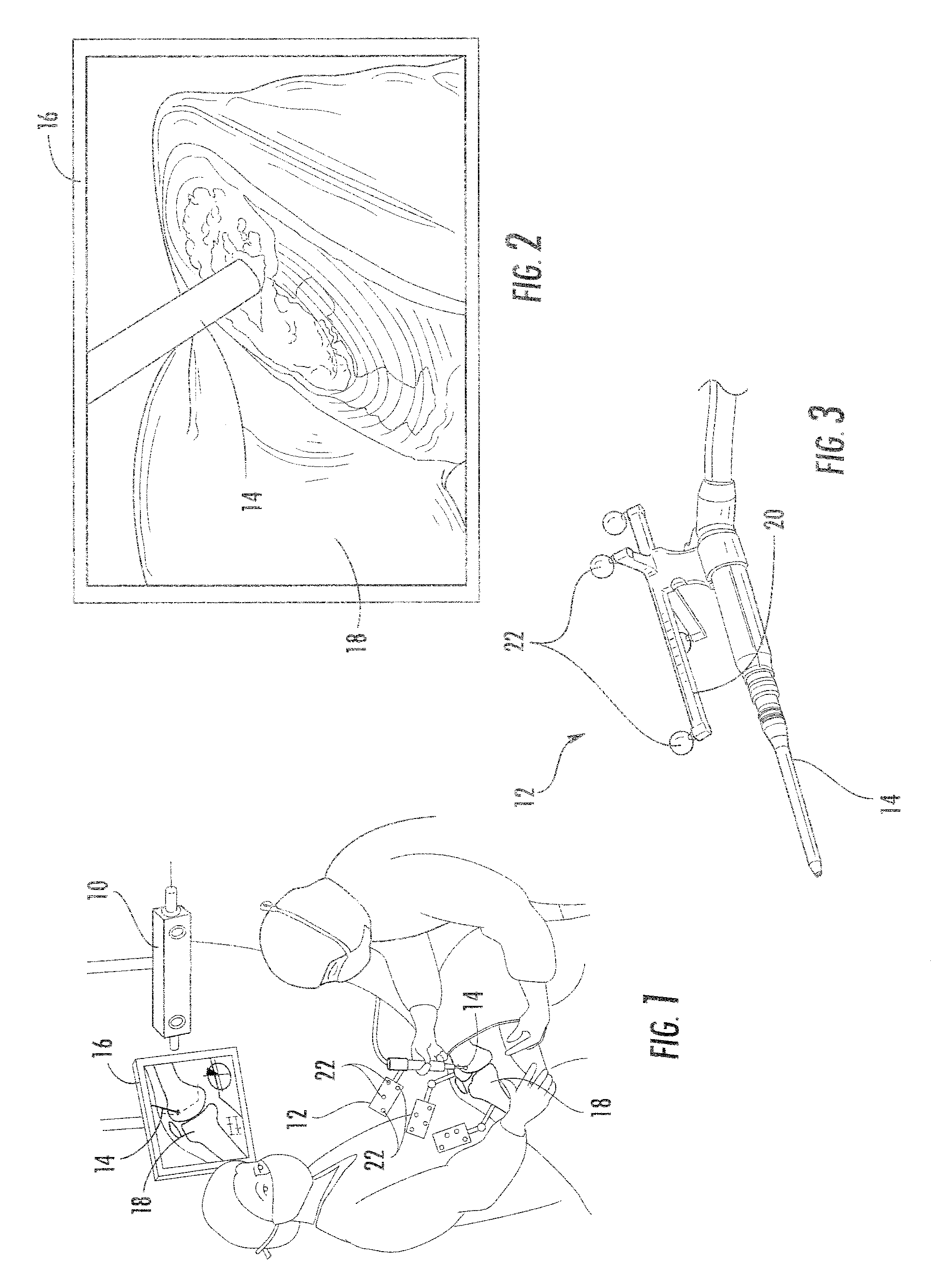
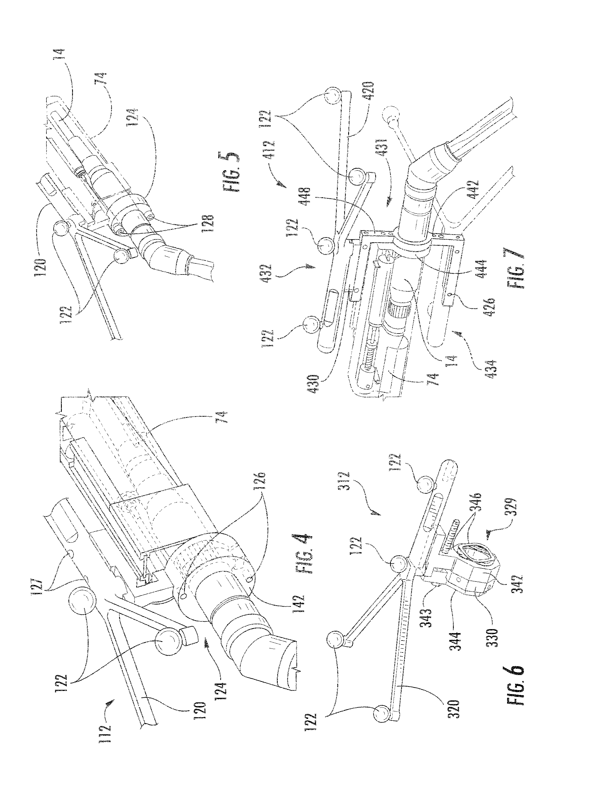
[0026]For purposes of the description hereinafter, the terms “upper”, “lower”, “right”, “left”, “vertical”, “horizontal”, “top”, “bottom”, “lateral”, “longitudinal” and related derivatives thereof shall relate to the invention as it is oriented in the drawings. However, it is to be understood that the present invention may assume various alternative variations and step sequences, except where expressly specified to the contrary. It is also to be understood that the specific devices and processes illustrated in the attached drawings, and described in the following specification, are simply exemplary embodiments of the invention. Hence, specific dimensions and other physical characteristics related to the embodiments disclosed herein are not to be considered as unduly limiting.

[0027]It is to be understood that the invention may assume various alternative variations and step sequences, except where expressly specified to the contrary. It is also to be understood that the specific devic...


PUM


Abstract

A reconfigurable tracking arrangement for an object includes a repositionable mounting arrangement that may be configured to releasably connect to an object for selectively positioning the same. The mounting arrangement may further include a first piece attached to the object and a second piece that can be repositioned relative to the first piece. In addition, the mounting arrangement may be configured to be secured in at least two stable pre-configured positions about the object.

Description

CROSS REFERENCE TO RELATED APPLICATION[0001]This application claims the benefit of priority of U.S. Provisional Patent Application Ser. No. 61 / 342,996, filed Apr. 22, 2010, on which this patent application is based and which is incorporated herein by reference in its entirety.FIELD OF THE DISCLOSURE[0002]The present disclosure relates generally to methods, processes, apparatus, and systems for adjustable configurations of a tracking arrangement for a navigated surgical tool. In one embodiment, the present invention is implemented to enhance at least one of access, usability, configuration and overall trackable envelope of the tool.BACKGROUND[0003]Optical navigation, as well as other navigation, is used in surgery to track a rigid body's location in space in relation to a tool. These systems often rely upon the use of a camera and markers, the positions of which are tracked by the camera as discuss further hereinbelow. Accordingly, using a known spacial relationship of the markers on...

Claims


Application Information

Patent Timeline
Patent Type & Authority Applications(United States)
IPC IPC(8): A61B5/05
CPCA61B19/5244A61B2019/5483A61B2019/5255A61B19/54A61B34/20A61B90/39A61B2034/2055A61B2090/3983
Inventor NIKOU, CONSTANTINOSHAHN, ADAMMCCANDLESS, BENJAMINHEIN, STEVE
Owner BLUE BELT TECH
Why Eureka
Try Eureka