Failure sign detection apparatus

a technology for failure signs and detection apparatuses, which is applied in the direction of instruments, testing/monitoring control systems, process and machine control, etc. it can solve the problems of device erroneously determined to have failed before it fails, device on the brink of failure may not be repaired or replaced at an appropriate time, and cannot be used in any control

Active Publication Date: 2011-10-27
DENSO CORP
View PDF7 Cites 13 Cited by
  • Summary
  • Abstract
  • Description
  • Claims
  • Application Information

AI Technical Summary

Benefits of technology

[0016]According to the present invention, there is provided a failure sign detection apparatus which enables repairing or replacing a vehicle-mounted device at an appropriate timing.

Problems solved by technology

However, there may occur a case where the device is erroneously determined to have failed before it fails actually, for example, if the value of a parameter of the device oscillates between a normal range and an abnormal range, and accordingly the abnormal state is detected a number of times during a short period of time.
However, since the information that the device is about to fail is not recorded and lost when the detection system is powered off, it is not possible to use this information in any control using the output of the oxygen sensor, or in the next fault detection.
As explained above, the technique disclosed in patent document 1 has a problem in that a device operating normally may be replaced for no reason, while the technique disclosed in patent document 2 has a problem in that a device on the brink of failure may not be repaired or replaced at an appropriate timing.

Method used


Image

  • Failure sign detection apparatus
  • Failure sign detection apparatus
  • Failure sign detection apparatus

Examples


first embodiment

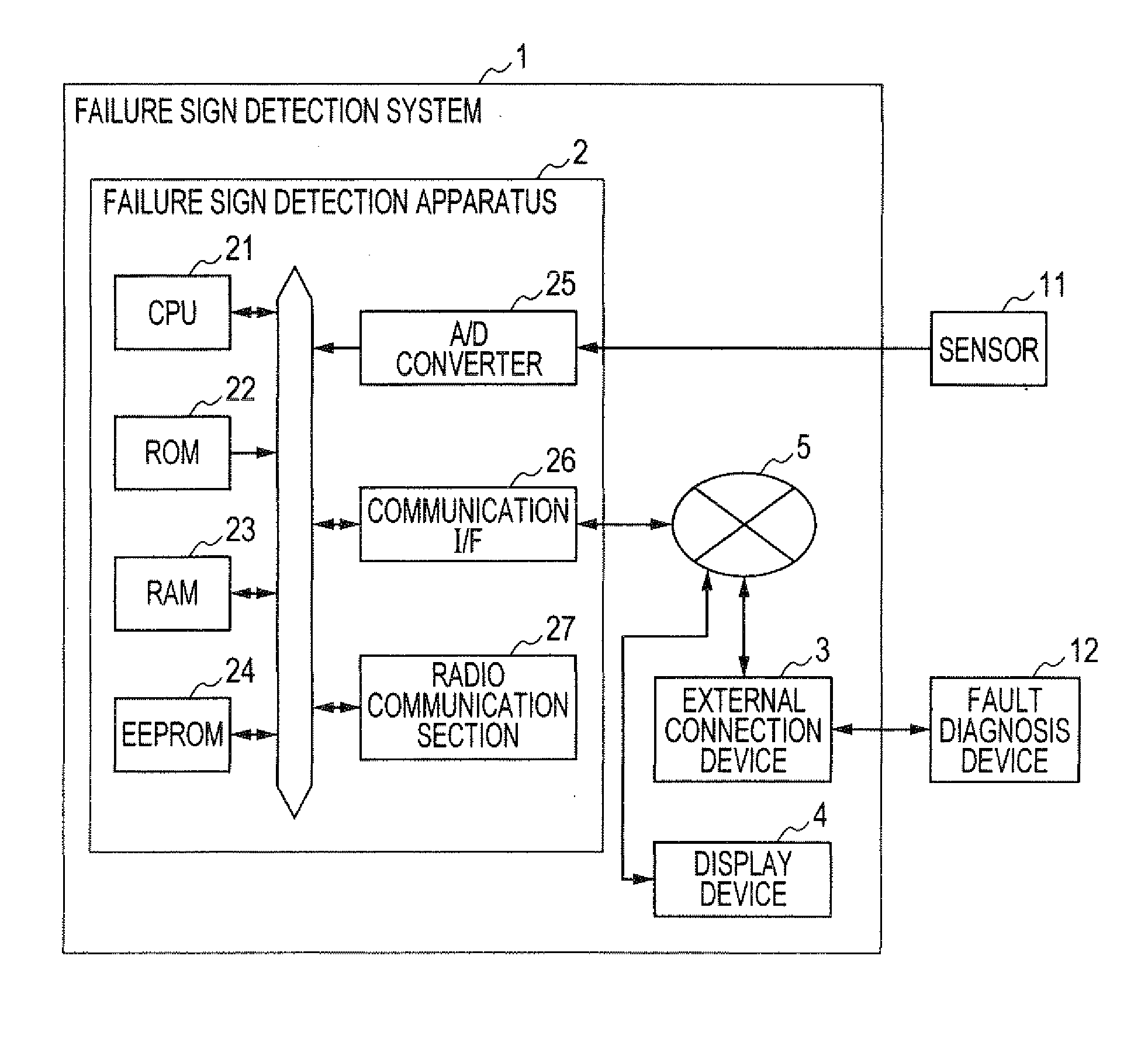
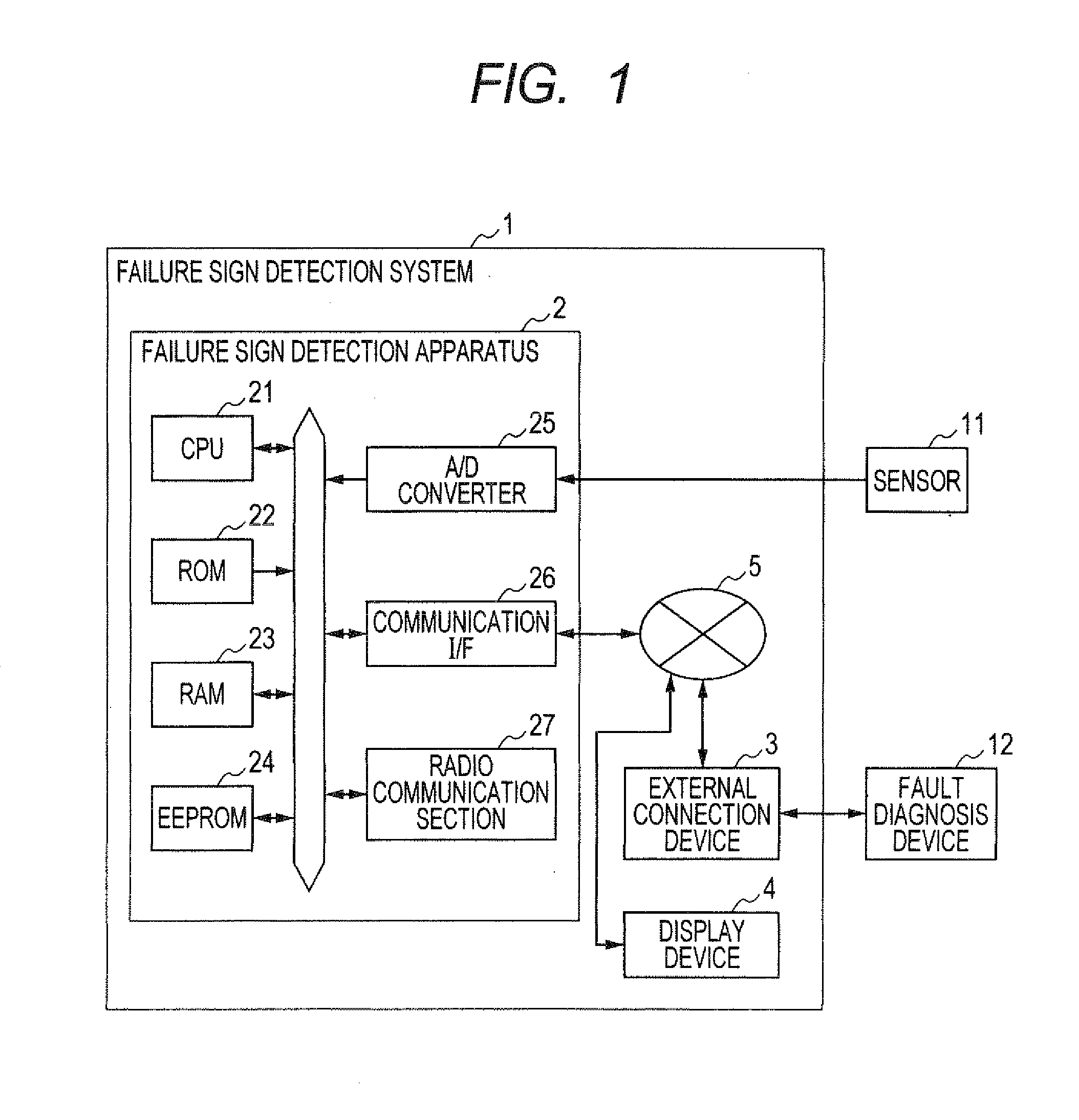
[0035]FIG. 1 is a block diagram showing the structure of a failure sign detection system 1 including a failure sign detection apparatus according to a first embodiment of the invention.

[0036]As shown in FIG. 1, the failure sign detection system 1 mounted on a vehicle is constituted of the failure sign detection apparatus 2, an external connection device 3, a display device 4 and an in-vehicle LAN 5. The failure sign detection apparatus 2 includes a CPU 21 to perform various processes in accordance with processing programs, a ROM 22 storing the processing programs, a ROM 23 to store various data, an EEPROM 24 capable of storing date therein with no power supplied, an A / D converter 25 to A / D-convert the output of a sensor 11 mounted on the vehicle, a communication interface (referred to as “I / F” hereinafter) 26 to connect the CPU 21 to the in-vehicle LAN 5, and a radio communication section 27 to exchange data with an external device outside the vehicle through wireless communication....

second embodiment

[0078]Next, a second embodiment of the invention is described with emphasis on the difference with the first embodiment.

[0079]The second embodiment differs from the first embodiment in that the failure sign determination value calculating process is modified. In the following, the failure sign determination value calculating process performed in the second embodiment is explained with reference to FIG. 10.

[0080]The failure sign determination value calculating process in the second embodiment is the same as that in the first embodiment except that steps S130 to S145 are added. In the second embodiment, after completion of step S120, the process proceeds to step S130 to determine whether or not there is a tendency that the values of the failure sign evaluation index If increase with time. If the determination result in step S130 is negative, the process is terminated.

[0081]If the determination result in step S130 is affirmative, the process proceeds to step S135 to make a determinatio...

third embodiment

[0088]Next, a third embodiment of the invention is described with emphasis on the difference with the first embodiment.

[0089]The third embodiment differs from the first embodiment in that the failure sign determination value calculating process is modified. In the third embodiment, the sensor 11 is an accumulator pressure sensor.

[0090]In the following, the failure sign determination value calculating process in the third embodiment is explained with reference to the flowchart of FIG. 12. The failure sign determination value calculating process in the third embodiment is the same as that in the first embodiment except that steps S5, S75, S85 and S160 to S180 are added.

[0091]In this embodiment, the failure sign determination value calculating process begins at step S5 where the CPU 21 sets the normal threshold depending on the load of the vehicle. For example, when the vehicle is driven roughly and harsh braking is applied frequently, the CPU 21 determines that the load of the vehicle...


PUM


Abstract

The failure sign detection apparatus includes an abnormality detection means to make a comparison between a failure detection parameter of a vehicle device mounted on a vehicle and a predetermined abnormality detection threshold, and make a determination whether there is an abnormality in the vehicle device based on a result of the comparison, a failure sign evaluation index calculation means to calculate a failure sign evaluation index for evaluating a sign of failure of the vehicle device based on an abnormality duration period over which the detected abnormality continues and a parameter threshold difference indicative of a difference between the abnormality detection threshold and the failure detection parameter, and a failure sign detection means to detect a sign of failure of the vehicle device based on the failure sign evaluation index calculated by the failure sign evaluation index.

Description

[0001]This application claims priority to Japanese Patent Application No. 2010-102185 filed on Apr. 27, 2010, the entire contents of which are hereby incorporated by reference.BACKGROUND OF THE INVENTION[0002]1. Field of the Invention[0003]The present invention relates to an apparatus for detecting a sign of failure of a vehicle-mounted device.[0004]2. Description of Related Art[0005]It is known to make a diagnosis to detect failure of a vehicle-mounted device, and record the result of the diagnosis in a nonvolatile memory. To make such a diagnosis, it is known to make a determination that failure has occurred only after an abnormal state was detected more than once in order to prevent an erroneous determination. For example, refer to Japanese patent application Laid-open No. 2004-330892 (patent document 1). In this technique, the number of times of occurrence of an abnormal state is recorded at system off. Here, “an abnormal state” is a state in which the value of a parameter of a ...

Claims


Application Information

Patent Timeline
Patent Type & Authority Applications(United States)
IPC IPC(8): G06F19/00
CPCB60R16/0232G05B23/0235G07C5/085G07C5/0816G05B23/0262
Inventor SAKAKIBARA, TADAAKIWATANABE, HIROKAZUNAKAGAKI, YOSHIOFUKUTA, KENJI
Owner DENSO CORP
Why Eureka
Try Eureka