
Variable vehicle body fixed framer and method

Inactive Publication Date: 2011-11-03
COMAU INC (US)
View PDF4 Cites 27 Cited by
  • Summary
  • Abstract
  • Description
  • Claims
  • Application Information

AI Technical Summary

Benefits of technology

[0009]A significant advantage of the present invention is the elimination of large, bulky side gate framing structures described above that were previously needed to support component tooling such as clamps, fixtures and other devices to hold loose or loosely connected components until they could be welded together or otherwise secured to one another.
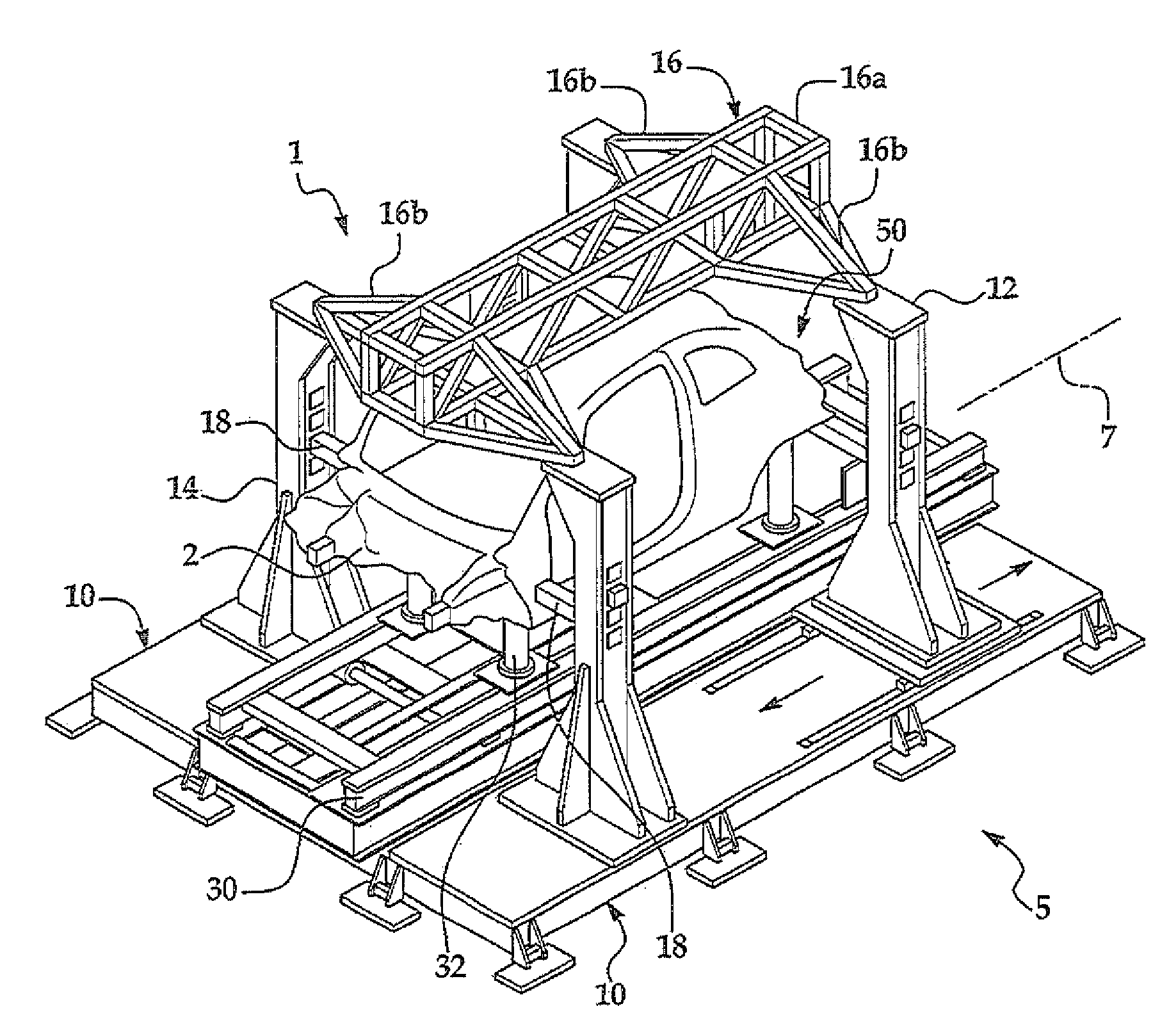
[0010]The present invention, through the exemplary use of only four principal pillars and a bridge positioned over the vehicle body, allows significantly more open space along the sides of the vehicle body for access and movement of robots and other equipment used to establish the critical geometry of vehicle body skeletal structure. An additional advantage of the elimination of the side gate structures is simplifying and reducing the amount of equipment on the assembly plant floor and the amount of assembly facility floor space needed for the storage and movement of the many vehicle side gate structures which were previously needed as each pair of side gates.
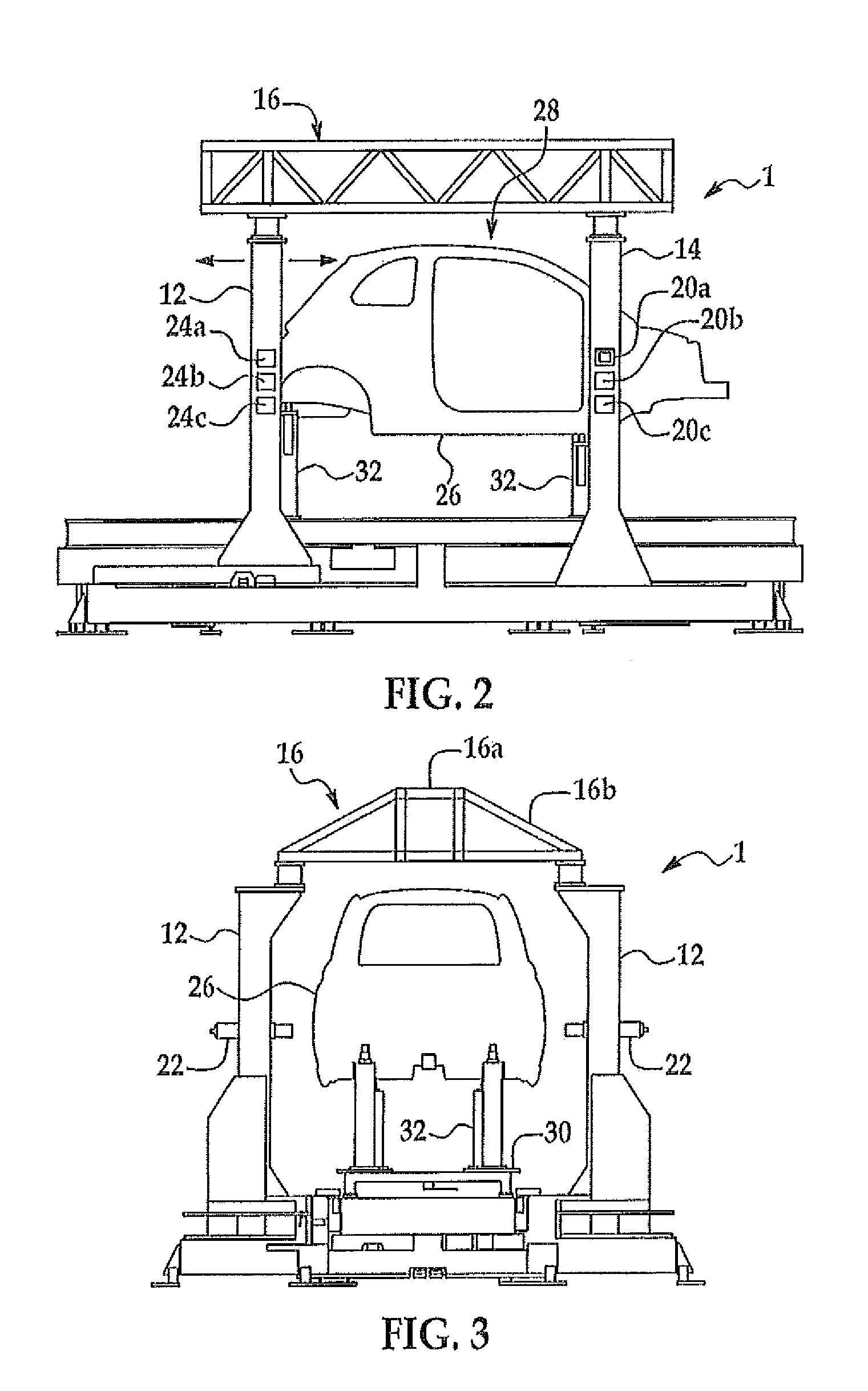
[0011]In one aspect of the invention, a primary body framing and geometry station is equipped with a pair of base members positioned on the floor of an assembly plant adjacent to both sides of the assembly line. A pair of front vertical pillars and a pair or rear vertical pillars are positioned on the base members (four pillars total, two on each base member). At least one of the pairs of pillars, for example the front pillars, may move longitudinally along the base members to accommodate different lengths of vehicle bodies to be built. The movable pair of pillars are accurately and precisely positionable and lockable to the base members. The pillars provide both four-way and two-way locating devices for accurately and precisely locating the body in the geometry-setting station so the build processes can be made to extremely close tolerances for a quality build.

Problems solved by technology

Demand for higher volumes of vehicles and efficient manufacturing and assembly of such vehicles has also increased further straining the objectives of accuracy, precision and quality of the end product.
These side gate frames often obstructed access to many areas along the vehicle body sides and above the vehicle to conduct the critical geometry processes at the primary framing station.
Where manual assembly operations were needed, the large and heavy side gates limited access to the vehicle body and logistically took up much space in the immediate area around the vehicle.
This was disadvantageous in numerous ways and created many challenges for a fast and efficient assembly process to construct the vehicle bodies.

Method used


Image

  • Variable vehicle body fixed framer and method
  • Variable vehicle body fixed framer and method
  • Variable vehicle body fixed framer and method

Examples


Embodiment Construction

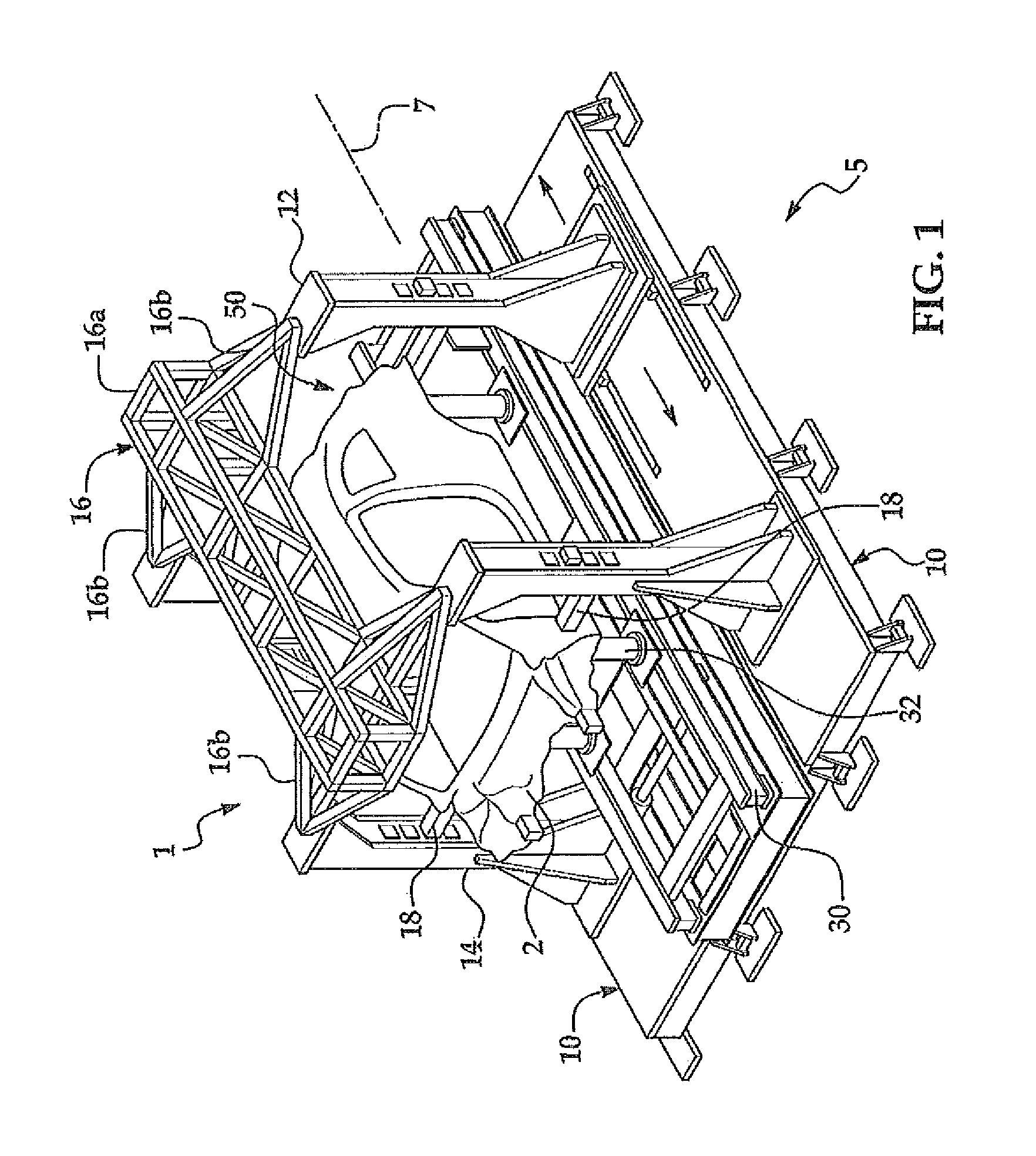
[0027]Examples of a variable vehicle body framer 1 in exemplary use at a body framing station 5 positioned along an assembly line 7 are shown in FIGS. 1-10. In an exemplary application, framer 1 is used to frame the body skeletal structure and establish the primary geometry of an automotive vehicle body 2. It is contemplated that other structures could be assembled using the present invention.

[0028]Referring to FIG. 1, in one example of framer 1, framer 1 includes parallel base members 10 suitably supported in spaced relation and mounted to a support surface, for example the floor of the motor vehicle assembly facility. A base, such as base members 10 can take many forms and serve to provide a structural support for the pillars, vehicle and bridge described below as well as human workers operating in the build station. For example, base 10 can be the assembly plant floor or other existing support structure suitable to support the pillars 12 / 14.

[0029]In the example shown, a pair of o...


PUM

PropertyMeasurementUnit
Lengthaaaaaaaaaa
Areaaaaaaaaaaa
Heightaaaaaaaaaa

Abstract

An vehicle body framing apparatus and method for use in assembling vehicle body structures of varying vehicle types in a framing station positioned along an assembly line. The apparatus includes an overhead bridge frame that is connected to two pairs of vertical pillars positioned at a build station. One pair of the pillars is moveable to accommodate different lengths of vehicle bodies. The spaced pillars and overhead bridge provide substantially unobstructed access openings to the body sides of the vehicle to increase efficiency and quality of build. The device and method may include a bridge frame storage and transport system for remotely storing the different bridge frames not in use and then transporting a selected bridge frame to the build station for use.

Description

CROSS REFERENCE TO RELATED APPLICATIONS[0001]This application claims priority benefit to U.S. Provisional Patent Application Ser. No. 61 / 329,918 filed Apr. 30, 2010, the entire contents of which is incorporated herein by reference.FIELD OF INVENTION[0002]This invention generally relates to motor vehicle body assembly systems.BACKGROUND OF THE INVENTION[0003]Increasing emphasis is placed on the accuracy and precision in manufacturing and assembly process, particularly in the field of passenger vehicles. Demand for higher volumes of vehicles and efficient manufacturing and assembly of such vehicles has also increased further straining the objectives of accuracy, precision and quality of the end product. Further demands have been placed on manufacturers to accommodate the changing demands for the type of vehicles to be built in a single manufacturing facility. Manufacturers need equipment and processes that allow to quickly switch between vehicle types or models that are built without ...

Claims


Application Information

Patent Timeline
IPC IPC(8): B23Q17/00B23P21/00
CPCB23K37/047B23K2201/006Y10T29/53022B62D65/18Y10T29/49764B62D65/024B23K2101/006
Inventor KILIBARDA, VELIBOR
Owner COMAU INC (US)
Learn More