
Lubrication Condition Monitoring

a technology of lubrication condition and monitoring method, which is applied in the direction of vibration measurement in solids, mechanical instruments, instruments, etc., can solve the problems of affecting the operation of the bearing, the dielectric constant of the oil changes, and the bearing loses its ability to effectively separate the rolling contact surface, etc., to achieve easy change and monitoring of the lubrication condition, and the operation conditions of the bearing remain essentially constant. , the effect of increasing the friction loss

Active Publication Date: 2011-11-03
AB SKF
View PDF3 Cites 31 Cited by
  • Summary
  • Abstract
  • Description
  • Claims
  • Application Information

AI Technical Summary

Benefits of technology

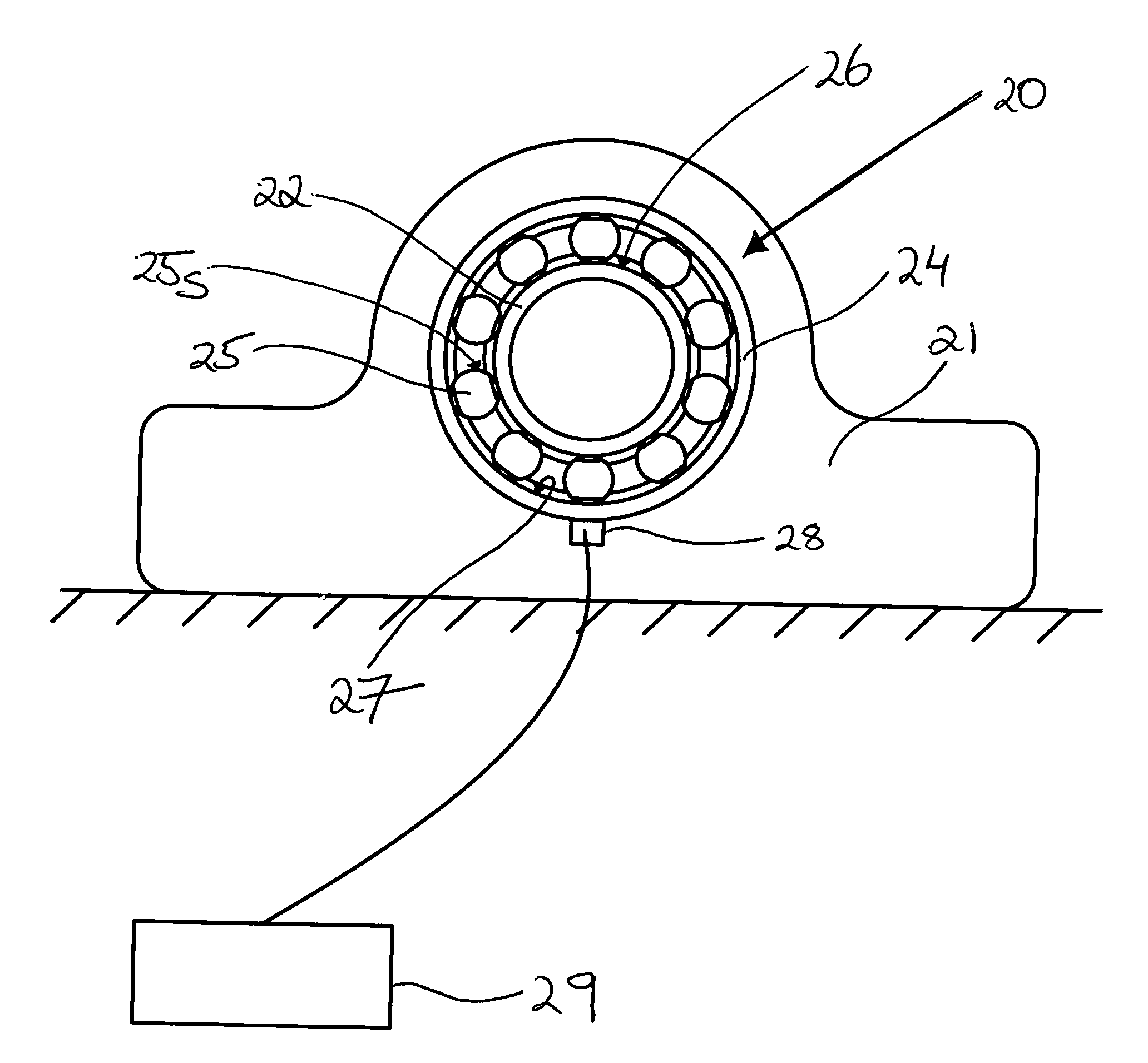
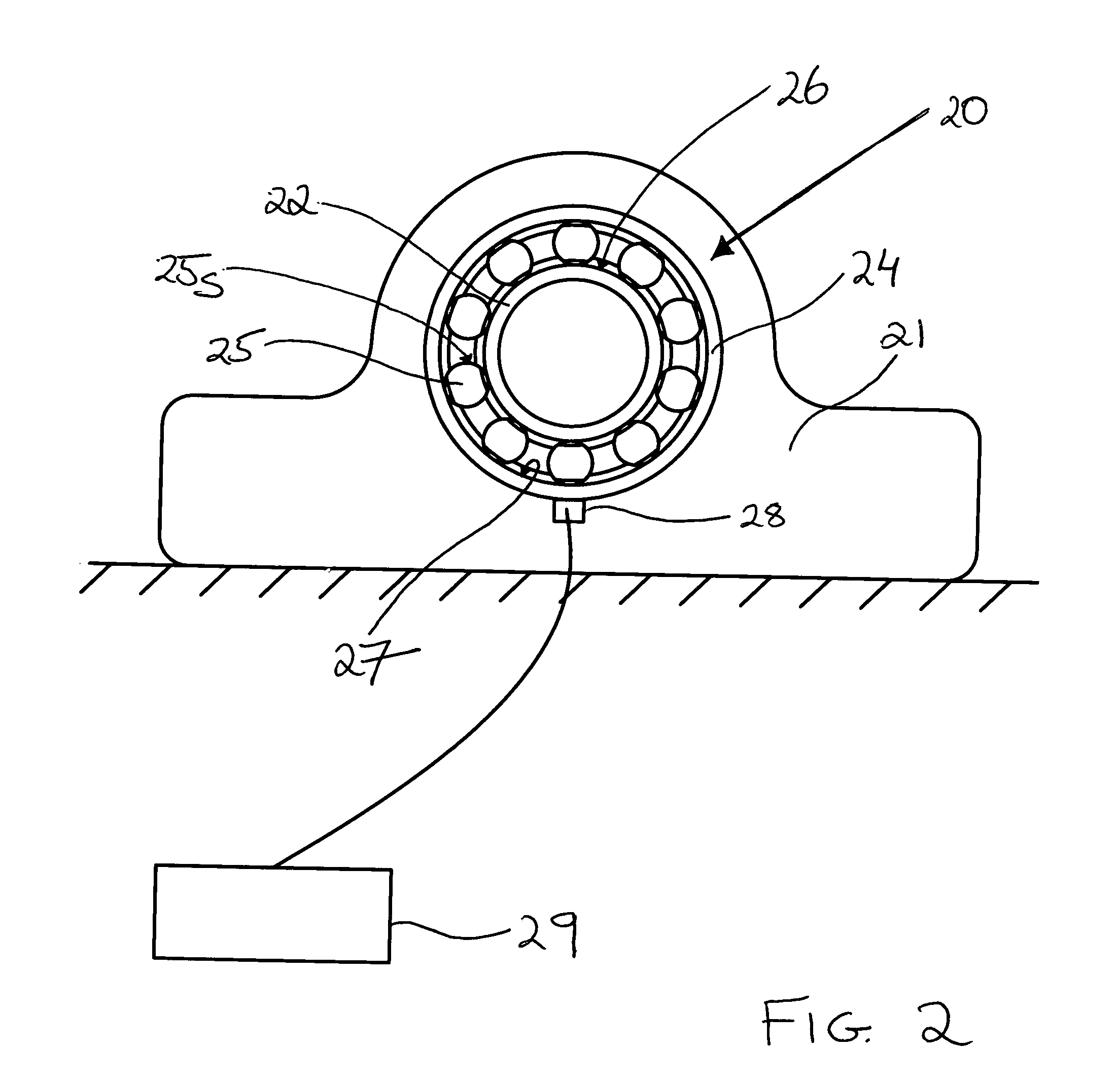
The present invention provides a method for monitoring the lubrication condition of an oil-lubricated rolling element bearing by measuring the level of acoustic emission generated in a bearing. The method involves measuring high-frequency structure-borne acoustic emissions generated as a result of asperity contact between the rolling surfaces of the bearing. The emitted acoustic energy is extracted from the measured signals and a lubrication parameter is determined based on a power-law relation between the emitted acoustic energy and the lubrication condition. The invention also includes an acoustic emission sensor and signal processing means for monitoring the lubrication condition. The invention allows for preventive action to detect abnormal bearing conditions before damage to the bearing occurs.

Problems solved by technology

A generous safety factor is built into the prescribed intervals, but when, for example, extreme contamination enters a circulating lubricant, the prescribed interval may be too short.
In other instances, the prescribed intervals can be excessively long, leading to the replacement of lubricant that still has a considerable useful life.
It has been found that the dielectric constant of an oil changes as the oil degrades and becomes contaminated.
And as an oil degrades, it loses its ability to effectively separate the rolling contact surfaces in a bearing.
It is necessary to interfere with the lubrication system and the condition of the lubricant cannot be monitored continuously.
If, for example, an oil filter becomes clogged, a bearing might experience a starved lubrication condition simply because its supply of oil is interrupted.
Also, the measurement method interferes with normal bearing operation.
Again, this is an intrusive method that can be detrimental to bearing operation.

Method used


Image

  • Lubrication Condition Monitoring
  • Lubrication Condition Monitoring
  • Lubrication Condition Monitoring

Examples


Embodiment Construction

[0041]The embodiments of the invention with further developments described in the following are to be regarded only as examples and are in no way to limit the scope of the protection provided by the patent claims.

[0042]In the inventive method described herein, Acoustic Emission (AE) signals are measured. A commonly accepted definition for AE is transient elastic waves within a material due to localized stress release. It is associated with a range of phenomena which generate broadband activity from the transient release of stored elastic energy from localised sources. The elastic stress waves are generated in the ultrasonic frequency range and are structure borne. The waveform detected by a sensor will therefore be distorted by frequency-dependent attenuation such as dispersion, multi-path propagation and mode conversion. Significant acoustic emission is associated with material deformation, fracture or frictional processes, where the emitted signal has a surface or subsurface origi...


PUM

PropertyMeasurementUnit
frequencyaaaaaaaaaa
acoustic energyaaaaaaaaaa
power-aaaaaaaaaa

Abstract

The present invention relates to a method of determining a lubrication parameter indicative of a lubrication condition of an oil-lubricated rolling element bearing. The method comprises measuring high-frequency structure-borne acoustic emissions generated by asperity contact between rolling contact surfaces of the bearing, to provide a measured signal. The emitted acoustic energy is then extracted from the measured signal and the lubrication parameter is determined from the acoustic energy. The determination is made on the basis of a power-law relation between acoustic energy and the lubrication parameter.

Description

TECHNICAL FIELD[0001]The present invention relates to a method for lubrication condition monitoring in an oil-lubricated rolling element bearing by measuring structure-borne acoustic emission.BACKGROUND ART[0002]In order for rolling element bearings to operate in a reliable way, they have to be adequately lubricated. The main purpose of the lubricant is to prevent metallic contact between the rolling elements, raceways and cages and thus to prevent wear of the bearing. The lubricant is also used to protect the bearing surfaces against corrosion. It is therefore important to choose both the proper lubricant and the proper lubrication method for each individual bearing application, as well as a correct maintenance program.[0003]In applications where the lubrication for a bearing or bearings needs to be replenished or replaced, this can be done on the basis of relubrication intervals prescribed by the bearing manufacturer or the supplier of a lubrication system for the bearings. A gene...

Claims


Application Information

Patent Timeline
Patent Type & Authority Applications(United States)
IPC IPC(8): G01N29/14
CPCF16C19/52F16C33/6688F16C33/6674F16C33/667
Inventor GANJI, ALIHOLSNIJDERS, JOZEF JOHANNES
Owner AB SKF
Learn More