[0013]It can be considered that an auxiliary device known in the prior art indeed could achieve a protection of the tool holder from dust, shavings or other comminuted material by incorporating a tool holder into a collecting chamber in a completely closed manner. However, an undesirable contact between the tool holder of the electrical work machine and the collecting chamber of the auxiliary device can nonetheless result in an undesirable
coupling and optionally noticeable force transfer. One aspect of the present invention is that a large decoupling of the auxiliary device from the electrical work machine, more particularly a decoupling of the tool holder from the collecting chamber, leads to an advantageous construction of the auxiliary device and the
system composed of an electrical work machine and the auxiliary device. It should be possible to effectively decouple the tool holder from the collecting chamber even in the case of disadvantageous loads. According to aspects of the concept of the invention, a decoupling is achieved, inter alia, by means of an opening that allows the tool holder to be freely accessible from the sides.
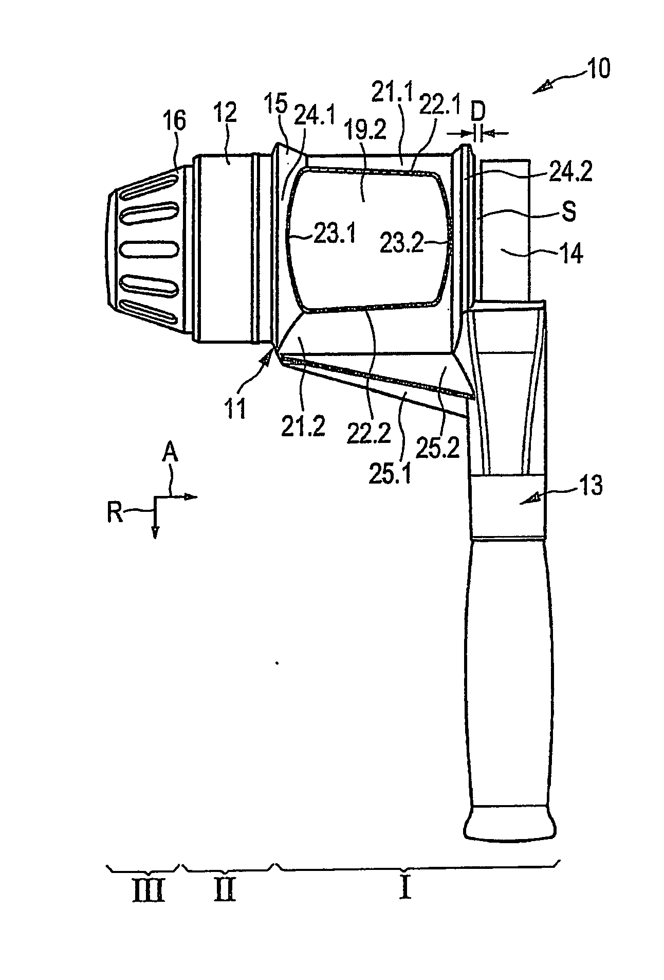
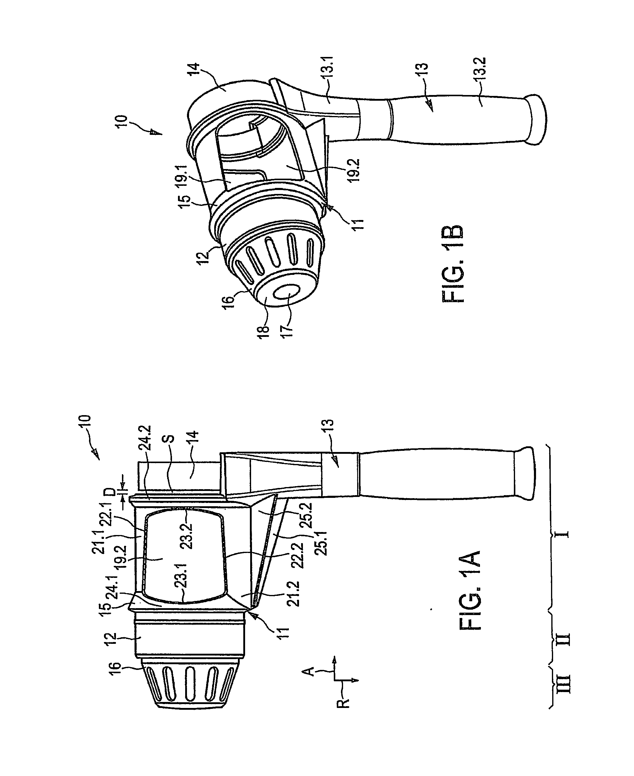
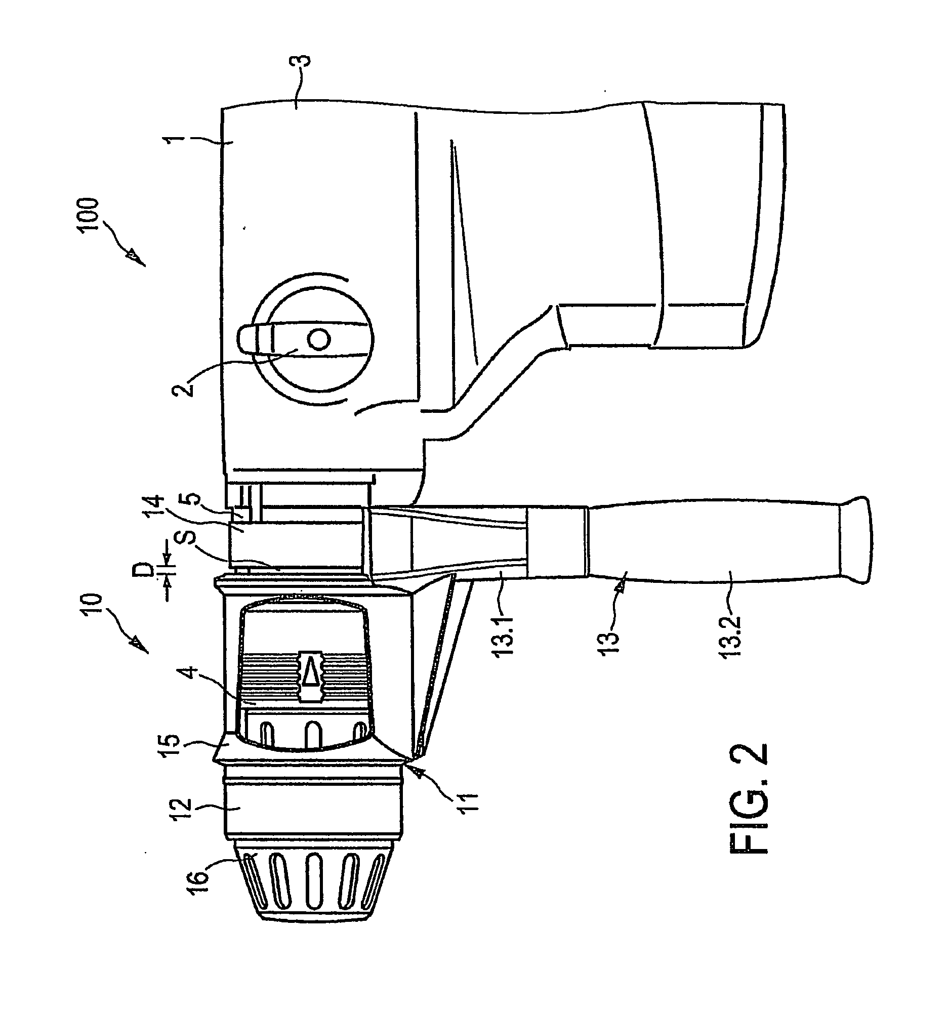
[0016]In a particularly preferred development, provision is made for the handling section and the attaching, device to be disposed side by side in an axial direction. In doing so, provision is made particularly for the handling section to be directly connected to the
handle, which protrudes in the radial direction, and still be disposed axially at a distance from the attaching device. In the preferred development, the handling section is not connected directly to the attaching device, but instead only indirectly connected to the attaching device by means of the handle. According to this development, a
free space is provided between the handling section and the attaching device. For example, the auxiliary device is provided with a handling section that is permanently connected to the handle, and the handle is permanently connected to the attaching device. On the whole, this preferably results in a practically U-shaped arrangement of the handling section, the handle, and the attaching device. Such an intrinsically vibratory, U-shaped arrangement enables a particularly advantageous absorption of impacts or the like and prevents or damps disadvantageous couplings between the auxiliary device and the electrical work machine. The housing comprising the handling section, the handle, and the attaching device is preferably formed integrally.
[0018]It has proved particularly advantageous if the handling section comprises at least one opening that allows the tool holder to be freely accessible, particularly from both sides. This makes the tool holder accessible with comparable ease even in the connected state of the auxiliary device so that the user can lock or unlock the same for mounting the tool. There is also an enlarged
free space made available for the tool holder, which free space can be utilized if the tool holder is displaced relative to the auxiliary device. An undesirable force-transferring contact between the tool holder and the auxiliary device is thus prevented as far as possible. Particularly preferably, the opening that allows the tool holder to be freely accessible from the sides can be delimited by axially extending axial struts and circumferentially extending annular struts. Thus the handling section can advantageously be provided in the form of an approximately cylindrical section of the housing having comparatively large openings, which section is made of at least one upper and one lower strut as well as a leading annular strut and a trailing annular strut. Furthermore, axial struts and / or annular struts give the handling section a certain absorbing or damping effect between the base component and the handle against impacts or shocks. Forces acting upon the base component or a front cap or any other connecting part such as a suction head or
processing head can be damped or absorbed by the handling section so that these forces are transferred in a reduced form or not transferred at all to the housing of the electrical work machine.
[0021]Preferably, at least the handling section and the handle are formed integrally. For example, the handling section and the handle can be provided comparatively easily in the form of a molded component. In a particularly preferred development, the base component can also be formed integrally with the handling section and the handle, more particularly as a molded component. Particularly preferably, a front cap disposed on the base component opposite to the handling section in the axial direction can also be formed integrally with the base component with comparative ease. In particular, the front cap and the base component can be formed integrally with the handling section as well as the handle. The housing of the auxiliary device according to this development is constructed so as to be intrinsically very stable and yet capable of absorbing shocks.
[0023]In this way, the base component can be designed very flexibly in order to attach various connecting parts such as a front cap, a suction head or a
processing head or a similar housing top to the base component, and to detach the same again, if necessary. For example, a base component can be provided with or without suction nozzles. A suction
nozzle has a suction connection for a suction
pipe. The suction
nozzle is very preferably inclined obliquely relative to an axial direction of the base component. The front cap preferably comprises an axial lead-through opening for the tool, which lead-through opening clasps the tool comparatively tightly. A front side of the front cap forms a very advantageous partition that acts against comminuted material so that the tool holder is very well-protected from the entry of comminuted material. A front cap constructed in this way very advantageously forms together with the base component a front cup comprising the collecting chamber for comminuted material.
[0024]It has proved advantageous if the material of the handle and / or the handling section is softer than the material of the base component. The effect of impacts and vibrations on the electrical work machine and the user is thus kept comparatively low or damped.

