Lubricant circuit

Inactive Publication Date: 2011-11-03
GM GLOBAL TECH OPERATIONS LLC
View PDF13 Cites 4 Cited by
  • Summary
  • Abstract
  • Description
  • Claims
  • Application Information

AI Technical Summary

Benefits of technology

In order that the second actuator does not block the movement of housing and rotor toward one another when it is separated from the distributor by the valve, the valve is preferably designed as a directional valve, which in one position in which it separates the second actuator from the distributor, connects it to the reservoir. Whereas the first actuator is generally connected to a downstream portion of the distributor in order to ensure that a requisite pressure is reached there, the valve is preferably connecte

Problems solved by technology

The cold start valve certainly offers effective protection from critically high pressures in the lubri

Method used


Image

  • Lubricant circuit
  • Lubricant circuit
  • Lubricant circuit

Examples


Embodiment Construction

The following detailed description is merely exemplary in nature and is not intended to application and uses. Furthermore, there is no intention to be bound by any theory presented in the preceding background or summary or the following detailed description.

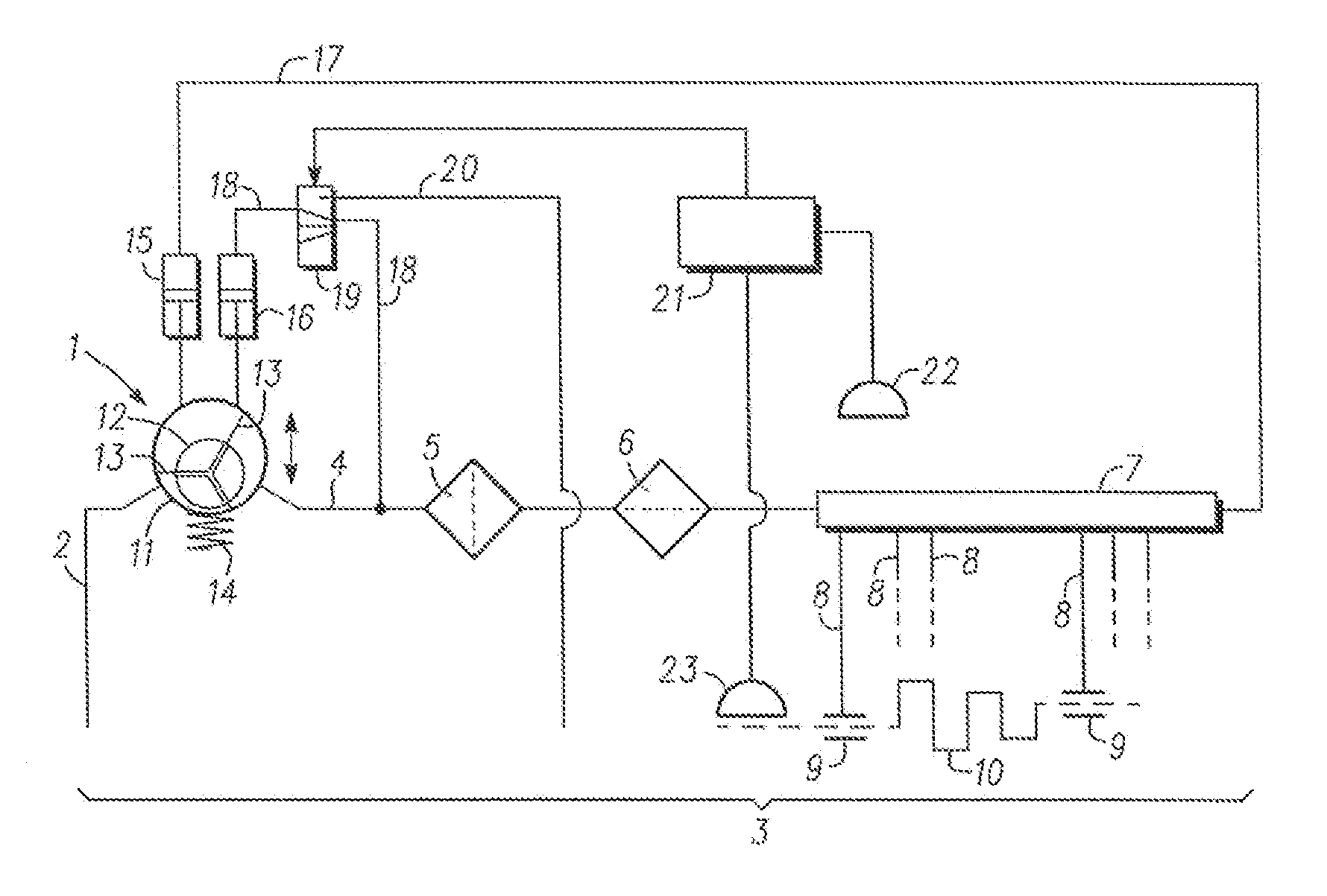
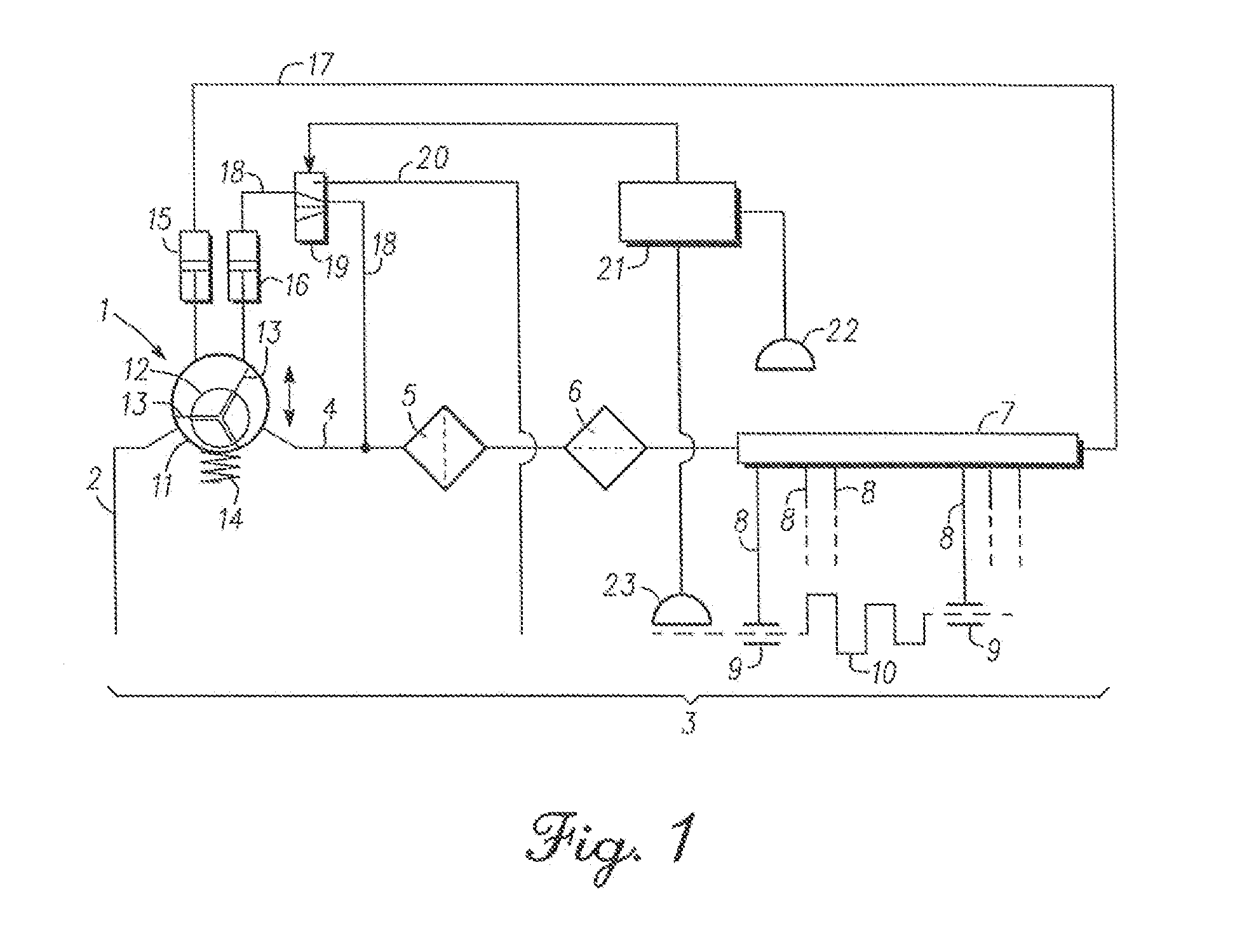
FIG. 1 shows a schematic diagram of an oil circuit in an automobile engine. A vane pump 1 is connected via a suction line 2 to an oil sump 3. A distributor connected to the vane pump 1 on the pressure side comprises a supply line 4, on which an oil filter 5 and an oil cooler 6 are disposed in series, and a gallery 7 from which branch lines 8 branch off to various lubricating points 9 of the engine such as bearings of a crankshaft 10. From the lubricating points 9 the oil runs back into the oil sump 3 unguided.

The vane pump 1 has in a manner known per se a housing 11 having a cylindrical cavity, in which there is provided a rotor 12 having a plurality of vanes 13 held by positioning rings in contact with an inner surface of the ho...


PUM


Abstract

A lubricant circuit includes, but is not limited to a lubricant pump, which is connected on the suction side to a reservoir and on the pressure side to a distributor, at least one lubricating point, which is connected to the distributor and a return leading to the reservoir, and an electronic control unit, which is set up to regulate the output pressure of the lubricant pump by reference to the temperature of the lubricant.

Description

CROSS-REFERENCE TO RELATED APPLICATIONThis application claims priority to German Patent Application No. 102010019007.1, filed May 3, 2010, which is incorporated herein by reference in its entirety.TECHNICAL FIELDThe technical field relates to a lubricant circuit, in particular for the lubrication of an internal combustion engine such as an Otto or diesel engine in an automobile.BACKGROUNDSince the lubricant requirement of such an internal combustion engine increases with its speed, the lubricant circuit usually comprises a lubricant pump firmly coupled to an output shaft of the internal combustion engine and driven by means of this. As a result of this coupling, the throughput of the lubricant pump increases with the speed of the internal combustion engine. Since the lubricant throughput of the engine is not exactly linearly proportional to the rotational speed, but depends on other factors, in particular the temperature of the internal combustion engine, the lubricant pump must be ...

Claims


Application Information

Patent Timeline
IPC IPC(8): F01M1/16F01M5/00
CPCF01M1/16F01M2250/60F01M2001/0246F01M2001/0238
Inventor ZWICKLER, GEORG
Owner GM GLOBAL TECH OPERATIONS LLC
Why Eureka
Try Eureka