Ophthalmologic apparatus and ophthalmologic observation method

a technology of ophthalmologic equipment and observation method, which is applied in the field of ophthalmologic equipment and ophthalmologic observation method, can solve the problems of not describing any method for accurately detecting the movement of an object, and the influence of an eye being scanned cannot be ignored, so as to achieve accurate detection of the movement of the obj

Active Publication Date: 2011-11-03
CANON KK
View PDF2 Cites 37 Cited by
  • Summary
  • Abstract
  • Description
  • Claims
  • Application Information

AI Technical Summary

Benefits of technology

[0014]According to the present invention, the influence on rotation and magnification detection due to the distortion of an image of an object, which is caused by the movement of the object during the acquisition of a single image, may be cancelled based on temporally successive images obtained by the scanning imaging system, which enables accurate detection of the movement of the object. In other words, the position of the object moving at high speed in a complicated manner may be accurately detected unlike the conventional technologies.

Problems solved by technology

The increase in the speed allows three-dimensional image taking of the fundus to be carried out, which has been difficult with the time domain method.
However, in three-dimensional imaging, two-dimensional scanning of the fundus is necessary even with the Fourier domain method, and hence the influence of an involuntary movement of an eye being scanned cannot be ignored.
However, the object of the invention disclosed in Japanese Patent Application Laid-Open No. 2006-235786 is to align images, each having a predetermined shift direction, into a single image, but does not describe any method for accurately detecting a movement of an object, for example, a complicated movement of an eye to be inspected.

Method used


Image

  • Ophthalmologic apparatus and ophthalmologic observation method
  • Ophthalmologic apparatus and ophthalmologic observation method
  • Ophthalmologic apparatus and ophthalmologic observation method

Examples


Embodiment Construction

[0022]An embodiment of the present invention is described in detail with reference to the attached drawings.

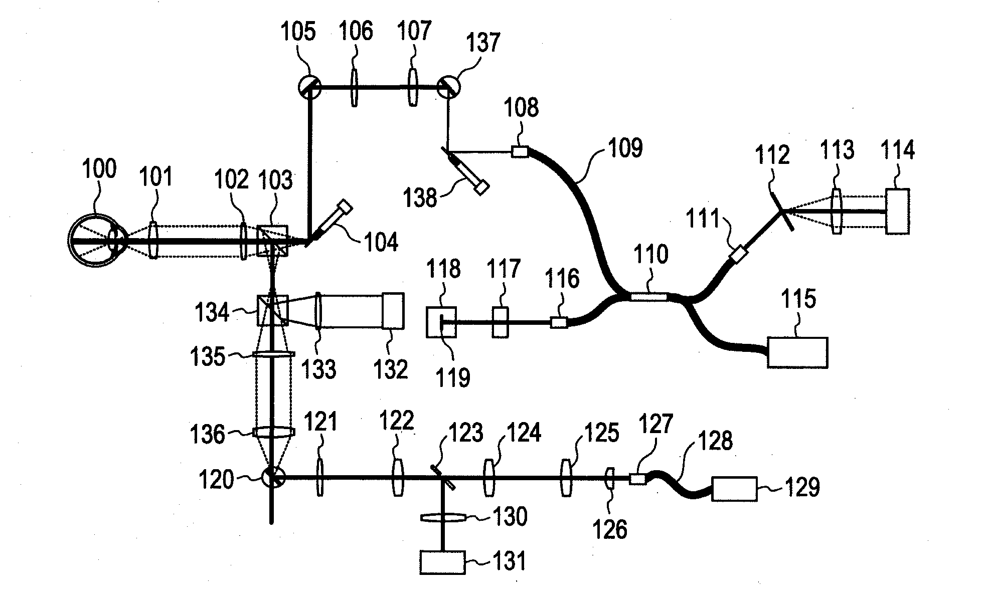
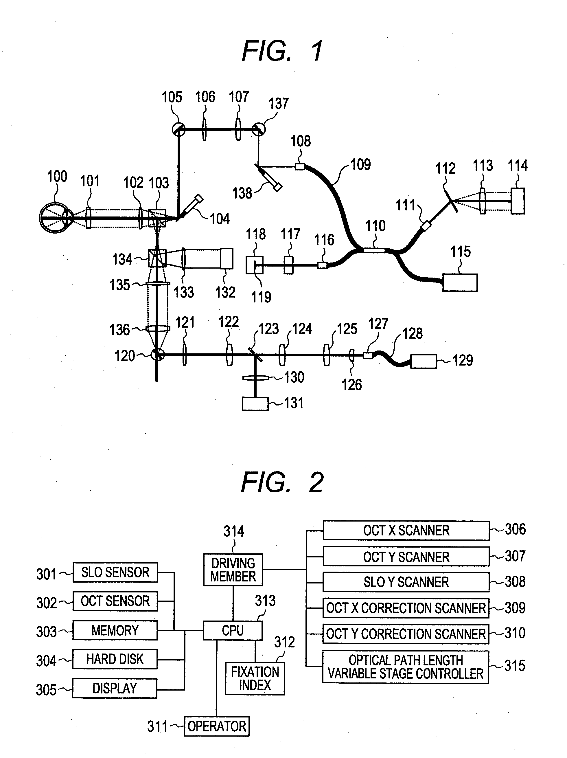
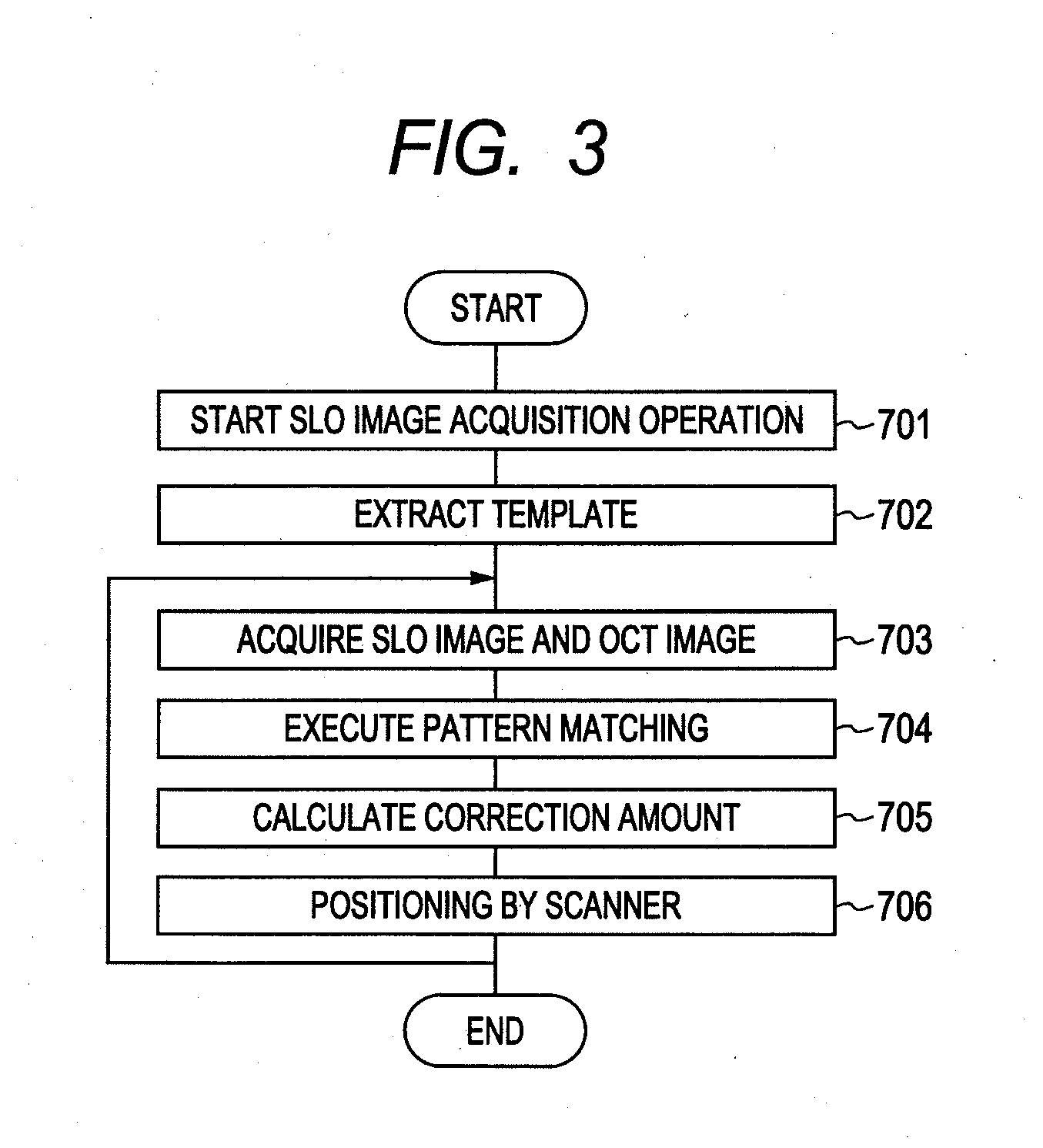
[0023]This embodiment describes a structure of an OCT apparatus for extracting templates (also referred to as “first characteristic points or first characteristic images”) from a fundus image (also referred to as “first fundus image”) (which is obtained by, for example, using a line-scan SLO), subjecting a newly (continuously) taken fundus image (also referred to as “second fundus image”) to pattern matching (exploring for the extracted characteristic images in the newly taken fundus image) to thereby detect an eye movement, and correcting a position of an OCT beam. The description is given with reference to an optical structure diagram of FIG. 1, a block diagram of FIG. 2, and a flowchart of FIG. 3, and a template diagram of FIG. 4. In this embodiment, a line scan SLO is used as a fundus movement detection apparatus. Any structure including a scanning imaging system, for exam...


PUM


Abstract

To accurately detect a movement of an object based on an image distorted by the movement of an eye to be inspected, which is acquired by a scanning imaging system, provided is an ophthalmologic apparatus including: an extraction means for extracting a plurality of characteristic images from a first fundus image of the eye to be inspected; a fundus image acquisition means for acquiring a second fundus image of the eye to be inspected during a period different from a period during which the first fundus image is acquired; and a calculation means for calculating at least a rotation of movements of the eye to be inspected based on the plurality of characteristic images and the second fundus image.

Description

BACKGROUND OF THE INVENTION[0001]1. Field of the Invention[0002]The present invention relates to an ophthalmologic apparatus for acquiring a tomographic image of an eye to be inspected, and an ophthalmologic observation method of observing the eye to be inspected.[0003]2. Description of the Related Art[0004]At present, various different types of optical equipment are used as ophthalmic equipments. Of those, an eye can be observed with various types of equipment including an anterior ocular segment photographing device, a fundus camera, a confocal scanning laser ophthalmoscope (SLO), and an optical coherence tomography (OCT) apparatus that is an optical coherence tomographic imaging apparatus using optical interference due to low coherence light beam. In particular, optical tomographic imaging apparatuses are designed to obtain a high resolution tomographic image of a fundus, and are currently on the way to becoming an indispensable apparatus in outpatient clinics specialized in abor...

Claims


Application Information

Patent Timeline
Patent Type & Authority Applications(United States)
IPC IPC(8): A61B3/14
CPCA61B3/102
Inventor NAKAJIMA, JUNKOUTSUNOMIYA, NORIHIKO
Owner CANON KK
Why Eureka
Try Eureka