
Internal gear grinding machine

a gear grinding machine and gear technology, applied in the direction of gear teeth, gear teeth, gear-teeth manufacturing apparatus, etc., can solve the problems of increasing the damage of threaded grinding wheels, the dresser, etc., and achieve the effect of reducing the size of the machine, saving space, and simplifying the entire dressing operation

Active Publication Date: 2011-11-03
MITSUBISHI HEAVY IND MACHINE TOOL CO LTD
View PDF8 Cites 11 Cited by
  • Summary
  • Abstract
  • Description
  • Claims
  • Application Information

AI Technical Summary

Benefits of technology

"The present invention aims to provide an internal gear grinding machine that can simplify dressing operation, reduce the size of the machine, and prevent damage to the tools even in abnormal situations such as a blackout. The solution provided is a machine that includes a dressing means for dressing the threaded tool with a disk-shaped dresser rotatable about a dresser rotation axis, and braking and maintaining means for applying a braking force to the dresser turning means, and maintaining the dresser at a turned position. This allows for easy and safe loading and unloading of gears, as well as efficient and safe grinding of internal gears."

Problems solved by technology

However, in the case where a dressing device for dressing a barrel-shaped threaded grinding wheel for grinding an internal gear is provided, dressing operation is complex due to limitations associated with the shape of an internal gear if this dressing device is just placed in an internal gear grinding machine.
This may increase the size of the machine.
When an abnormal situation such as a blackout occurs in such a meshing condition, the threaded grinding wheel, the dresser, and the like may be damaged.

Method used


Image

  • Internal gear grinding machine
  • Internal gear grinding machine
  • Internal gear grinding machine

Examples


embodiment

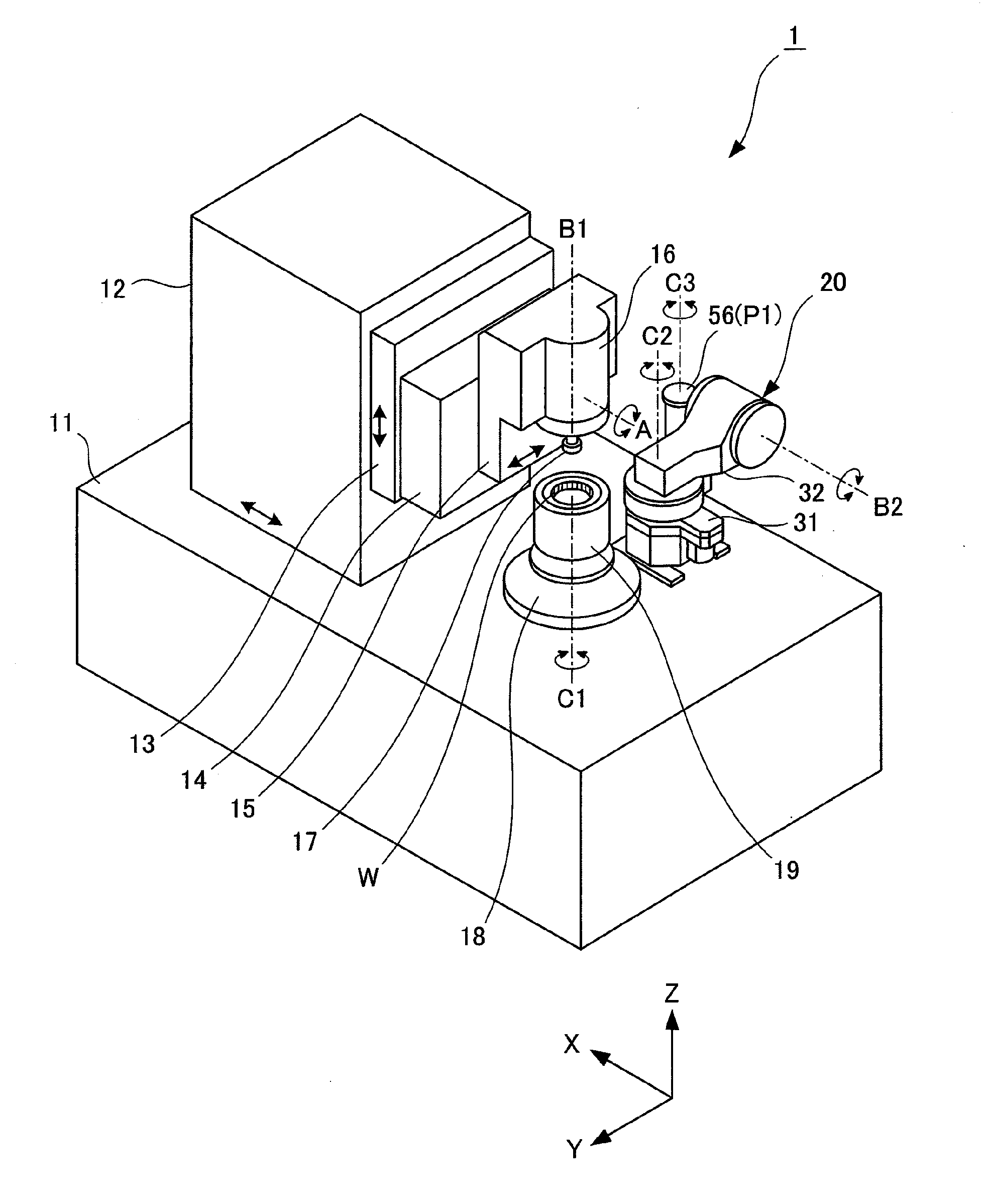
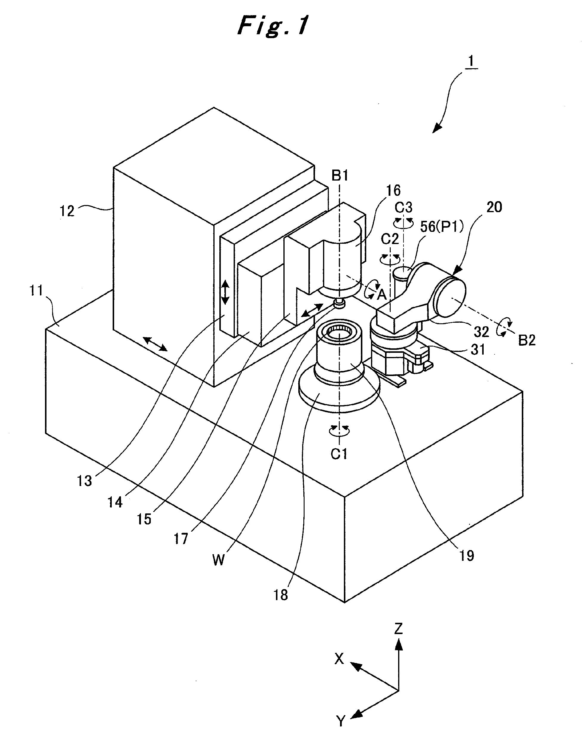
[0025]As shown in FIG. 1, a column 12 is supported on a bed 11 of an internal gear grinding machine 1 to be movable in the direction of a horizontal X axis. On the column 12, a saddle 13 is supported to be movable up and down in the direction of a vertical Z axis. On this saddle 13, a turning head 14 is supported to be turnable about a horizontal grinding wheel pivot axis A. On the turning head 14, a slide head 15 is supported to be movable in the direction of a horizontal Y axis. This slide head 15 is provided with a grinding wheel head 16.

[0026]On the grinding wheel head 16, a grinding wheel arbor 16a (see FIG. 8) is supported to be rotatable about a grinding wheel rotation axis B1. To the lower end of this grinding wheel arbor 16a, a barrel-shaped threaded grinding wheel (threaded tool) 17 is removably attached. Details of this will be described later. Accordingly, driving the turning head 14 and the grinding wheel head 16 causes the threaded grinding wheel 17 to pivot about a gr...


PUM

PropertyMeasurementUnit
shaft angleaaaaaaaaaa
shapeaaaaaaaaaa
braking forceaaaaaaaaaa

Abstract

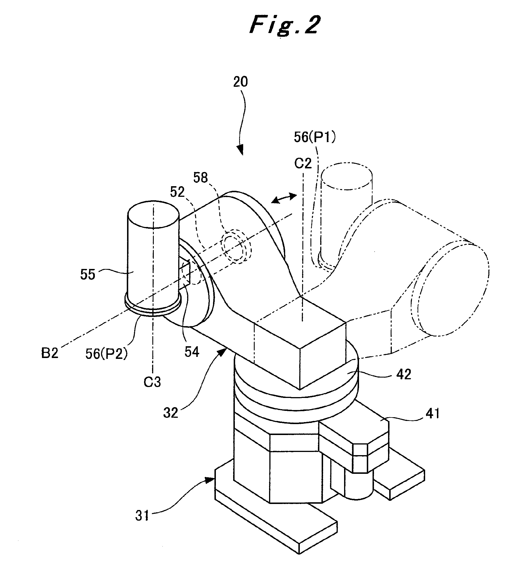
An object is to provide an internal gear grinding machine which makes it possible to achieve space savings and reduce the size of a machine, as well as to prevent the tools from being damaged even when an abnormal situation such as a blackout occurs, by simplifying dressing operation. To achieve the object, an internal gear grinding machine for use in grinding a workpiece (W) by synchronously rotating the workpiece (W) and a barrel-shaped threaded grinding wheel (17) in mesh with each other includes a dressing device (20) for dressing the threaded tool (17) by meshing the threaded grinding wheel (17) with a disk dresser (56). At the time of dressing, the threaded grinding wheel (17) and the disc dresser (56) are operated in accordance with the helix angle and barrel shape of the threaded grinding wheel (17), and the brake mechanism (58) applies a braking force to a dresser turn drive motor (53) to enable the disc dresser (56) to be maintained at a turned position thereof.

Description

TECHNICAL FIELD[0001]The present invention relates to an internal gear grinding machine for grinding an internal gear with a barrel-shaped threaded tool, and particularly to an internal gear grinding machine having the dressing function of dressing a barrel-shaped threaded tool.BACKGROUND ART[0002]Heretofore, gear grinding machines have been provided to efficiently finish the faces of the teeth of a heat-treated gear by grinding the gear with a threaded grinding wheel, which is a grinding tool. The sharpness of the threaded grinding wheel decreases due to the wear thereof as grinding is repeated. Accordingly, after a predetermined number of gears have been ground, the worn threaded grinding wheel needs to be dressed to restore the sharpness of the faces of the threads thereof.[0003]For this reason, conventional gear grinding machines have the dressing function of dressing a worn threaded grinding wheel with a dresser. Such a gear grinding machine having the dressing function is disc...

Claims


Application Information

Patent Timeline
Patent Type & Authority Applications(United States)
IPC IPC(8): B23F1/00
CPCB24B53/075B23F23/1225B23F5/04B24B53/12Y10T409/101431
Inventor OCHI, MASASHIYANASE, YOSHIKOTO
Owner MITSUBISHI HEAVY IND MACHINE TOOL CO LTD
Learn More