
Cognitive Loudspeaker System

a loudspeaker and cognition technology, applied in the field of sound production systems, can solve the problems of limiting the future expansion of this device, affecting the quality and effect of audio, and the audio processor 102/b> is a relatively expensive device, so as to achieve the effect of easy modification/upda

Active Publication Date: 2011-11-03
TAM KIT S
View PDF18 Cites 34 Cited by
  • Summary
  • Abstract
  • Description
  • Claims
  • Application Information

AI Technical Summary

Benefits of technology

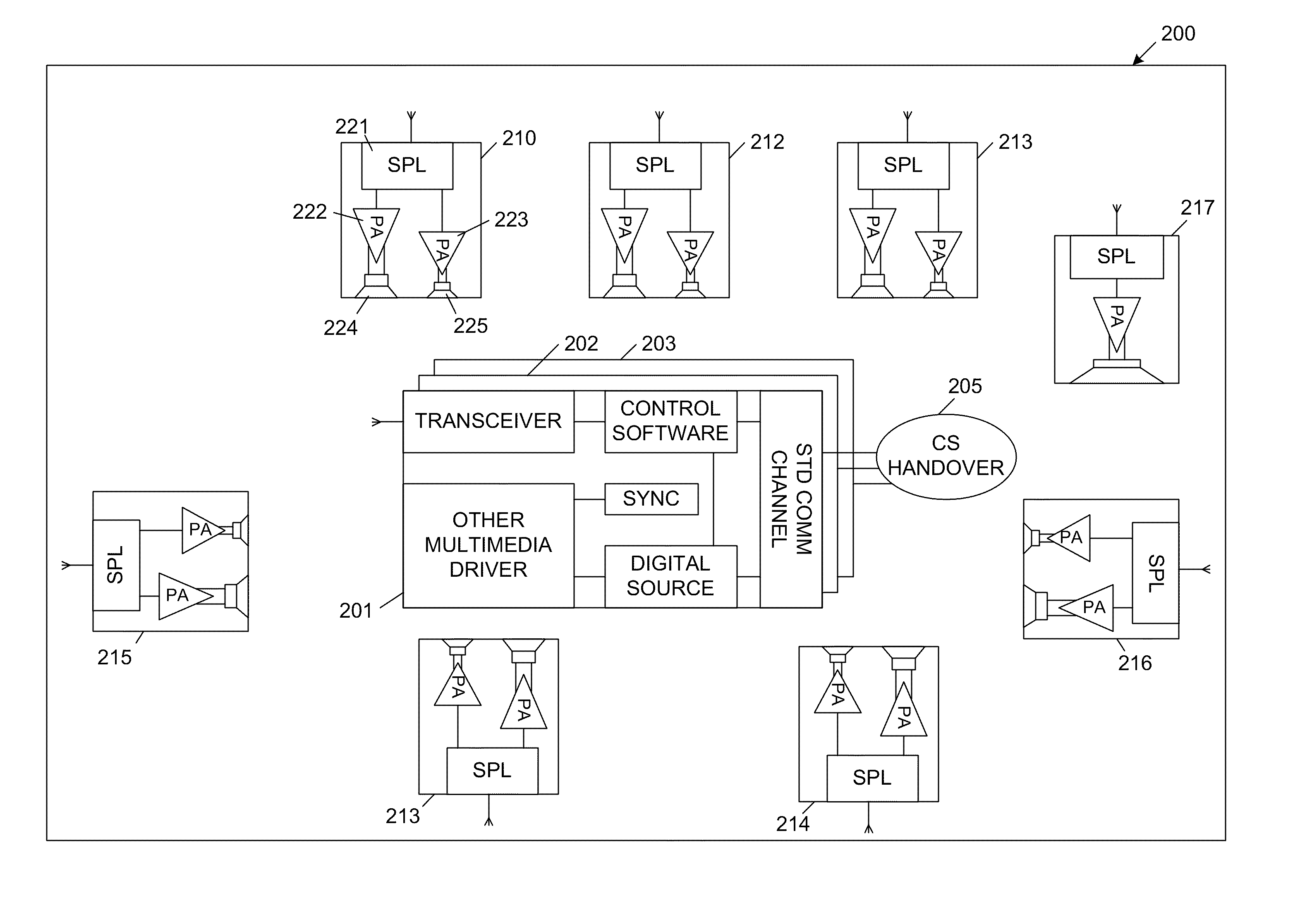
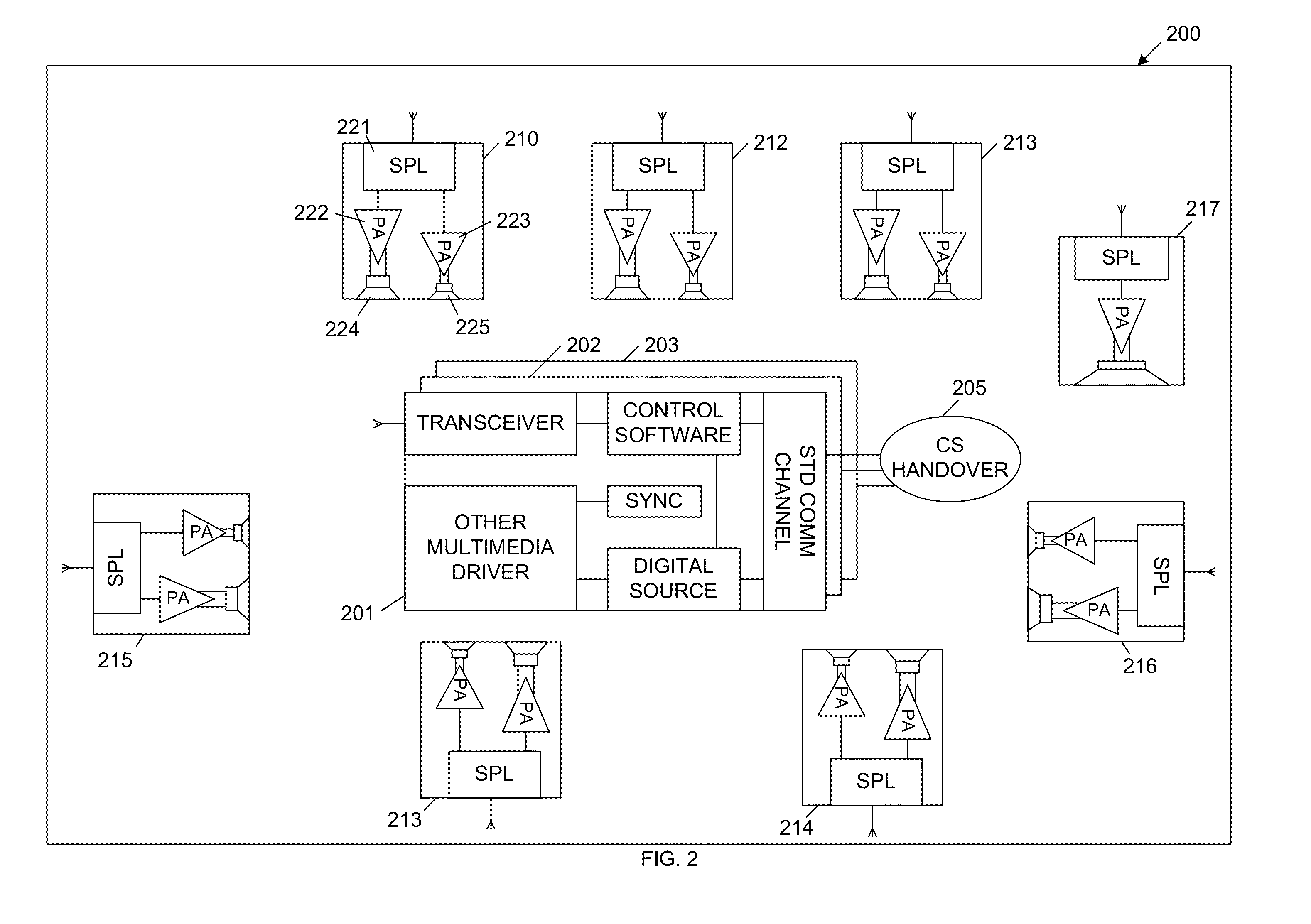
In accordance with one embodiment of the present invention, the active control station establishes a virtual decoder within each of the sound production stations, which enables playback from various sources. Cross-over filtering, compensation and equalization can be independently implemented within each sound production station. The virtual decoder allows the cognitive loudspeaker system to be easily modified / updated to handle new coding protocols.

Problems solved by technology

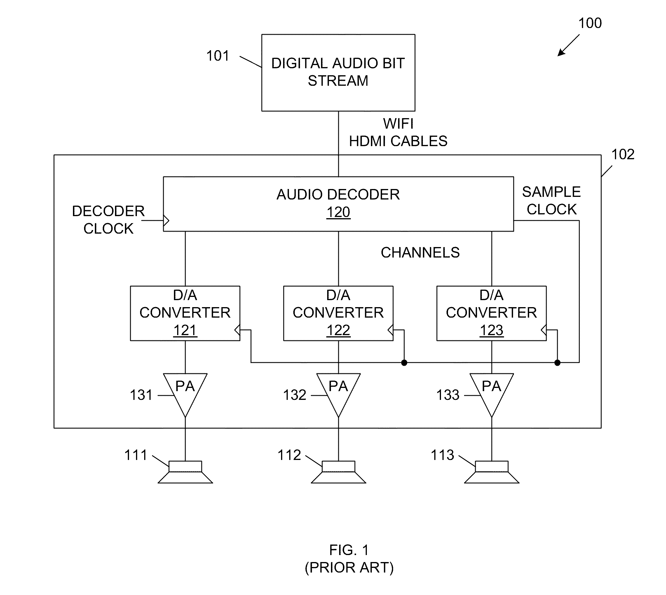
The audio quality and effect will suffer if the sample clock for each channel is out of synchronization.
As a result, audio processor 102 is a relatively expensive device.
Moreover, audio processor 102 implements preset signal processing and decoding functions, which may limit the future expansion of this device.
Market research has shown that the routing of speaker wires is a major obstacle for the adoption of surround sound systems.
However, this model still exhibits the problems described above.
The traditional electro-mechanical methods for improving loudspeaker sound quality are very expensive.
As described above, this creates a very significant inconvenience for adopting a surround sound system.
In this case, the audio processor 102 must include a wireless transmitter, undesirably increasing the cost and complexity of this device.
Note that by transmitting a subset of the audio channels wirelessly, while transmitting the remaining audio channels through speaker cables, the sound quality and the surround effect can be significantly compromised.

Method used


Image

  • Cognitive Loudspeaker System
  • Cognitive Loudspeaker System
  • Cognitive Loudspeaker System

Examples


Embodiment Construction

In general, the present invention provides a cognitive loudspeaker system for playback from digital audio sources. The cognitive loudspeaker system includes an active control station (CS) and one or more sound production stations (SPSs), which include the loudspeakers of the system. The various components of the cognitive loudspeaker system communicate wirelessly via a synchronized ultra-wideband (UWB) interface. The active control station can be flexibly associated with the sound production stations. An inactive control station can be switched to become the active control station using a control station handover process, which is described in more detail below. The sound production stations are source coding neutral. That is, the active control station establishes a virtual decoder within each of the sound production stations, which enables playback from various sources. Cross-over filtering, compensation and equalization can be independently implemented within each sound productio...


PUM


Abstract

A cognitive loudspeaker system including a control station that communicates wirelessly and bi-directionally with a plurality of sound production stations. The control station and the sound production stations are initially synchronized to a conductor clock. Configuration information is then transmitted from the sound production stations to the control station. In response, the control station generates playback executables, which are transmitted to the sound production stations. The control station also transmits digital audio information to the sound production stations. Within each sound production station, the previously received playback executable is used to control the decoding and processing of the received digital audio information. Each sound production station generates digital audio output samples, which are converted to analog output signals. These analog output signals are amplified and are used to drive loudspeakers.

Description

FIELD OF THE INVENTIONThe present invention relates to a sound production system for digital audio sources.RELATED ARTFIG. 1 is a block diagram of a conventional digital audio playback system 100, which includes a digital audio source 101, an audio processor 102, and loudspeakers 111-113. Digital audio source 101 provides a digital audio bit stream to audio processor 102. The digital audio bit stream can be transmitted, for example, over an HDMI cable or using a wireless transmission protocol (WiFi). The digital audio bit stream can be provided by an audio source, such as Internet radio, digital radio or a personal media device. The digital audio bit stream can alternately be provided by an audio-video source, such as streaming video from the Internet, blue-ray discs, DVDs or DVBs.Audio processor 102 includes an audio decoder 120, which receives the digital audio bit stream from digital audio source 101. The digital audio bit stream is played back in multiple channels in order to re...

Claims


Application Information

Patent Timeline
IPC IPC(8): G06F17/00
CPCH04S3/008H04R2227/005H04R2420/07
Inventor TAM, KIT S.
Owner TAM KIT S
Learn More