
Circuit configuration having a transceiver circuit for a bus system and nodes for a bus system

a technology of bus system and circuit configuration, which is applied in the field of circuit configuration having a transceiver circuit and a bus system node, can solve the problems of short delay in switching from idle mode to operating mode, and achieve the effect of reducing power consumption of the circuit, short delay in changing, and shortest possible tim

Active Publication Date: 2011-11-03
ROBERT BOSCH GMBH
View PDF8 Cites 9 Cited by
  • Summary
  • Abstract
  • Description
  • Claims
  • Application Information

AI Technical Summary

Benefits of technology

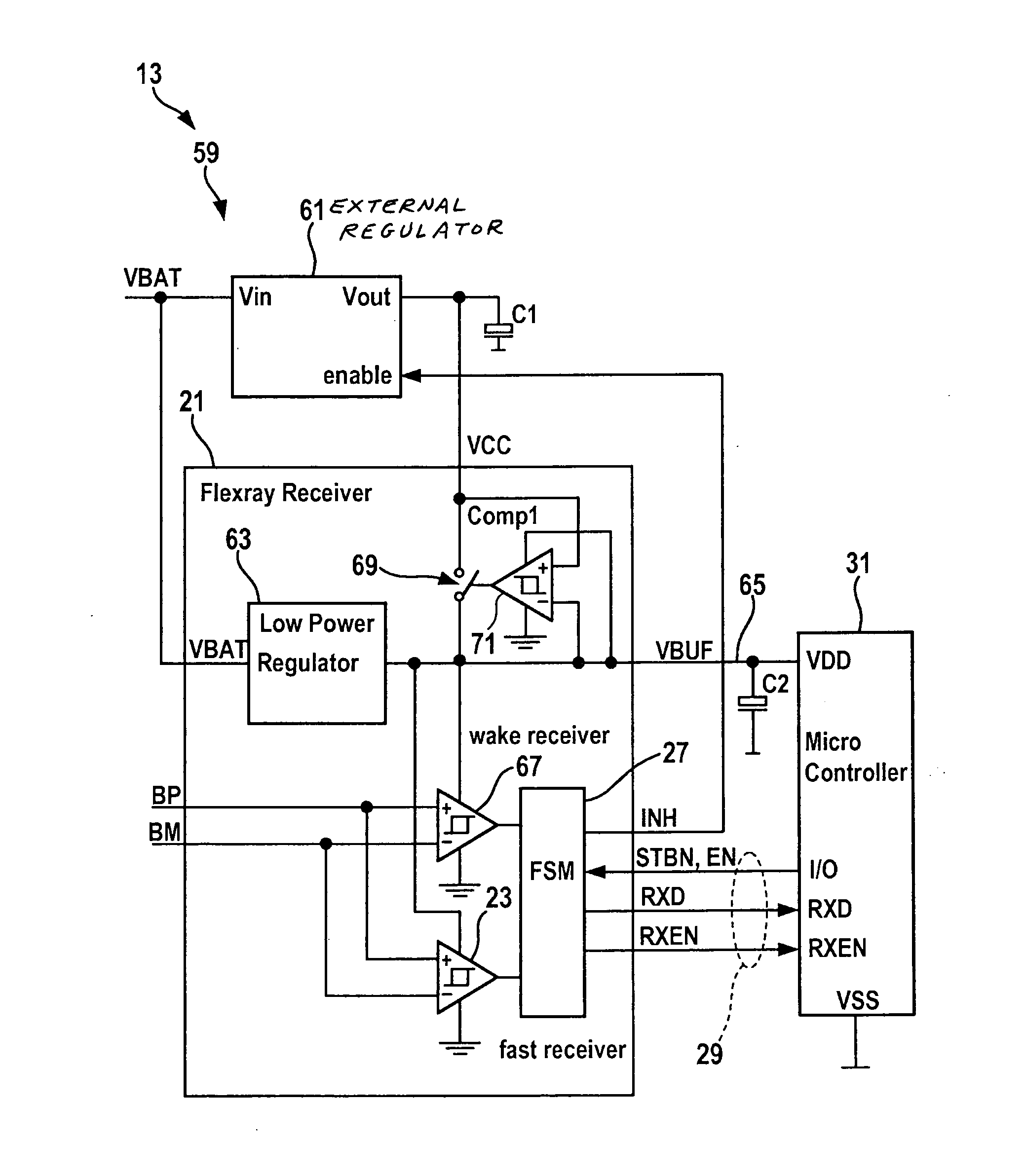
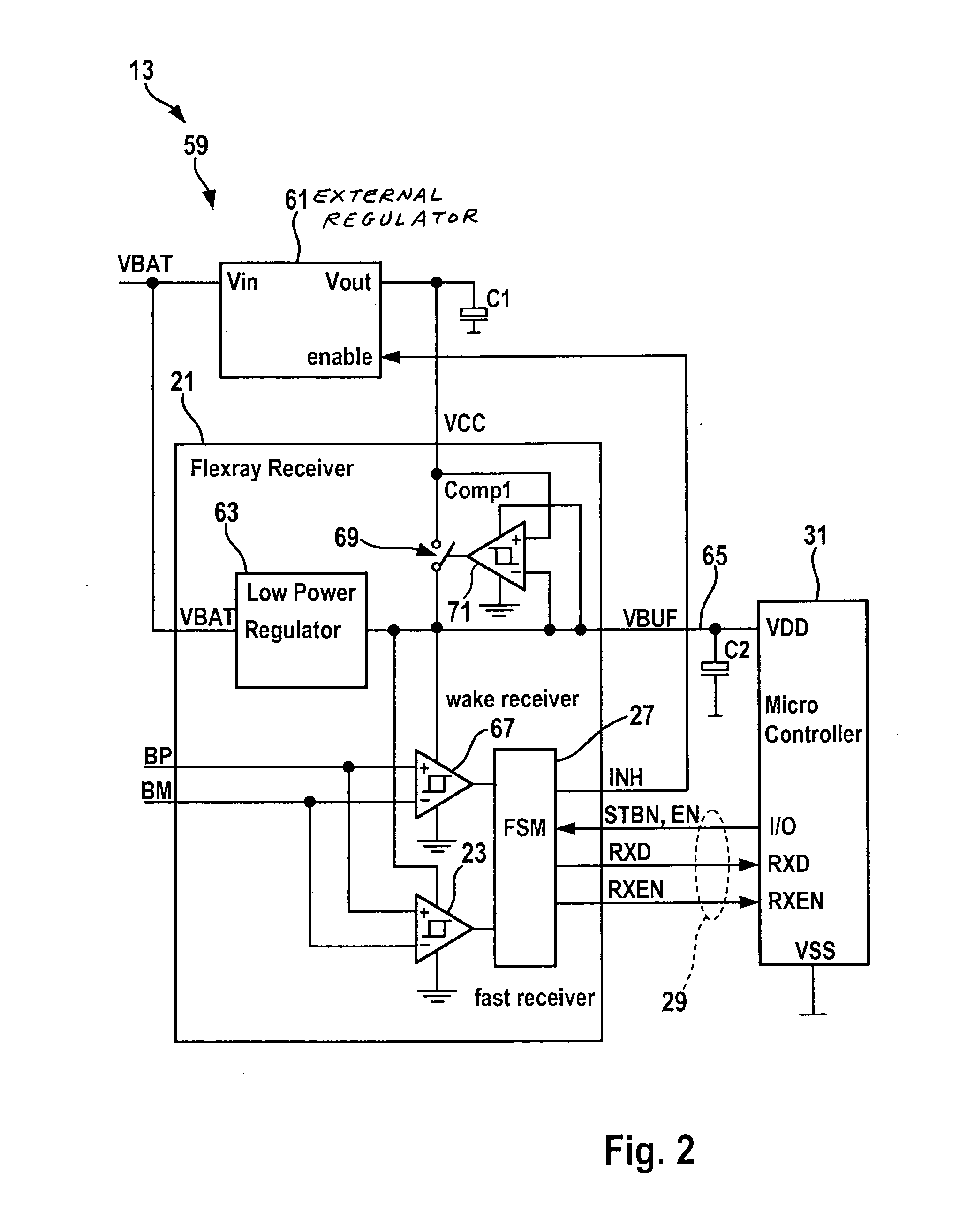
[0007]An object of the present invention is to provide a circuit configuration for a node having a transceiver circuit for a bus system in which a change from an idle mode to an operating mode is possible in the shortest possible time.
[0009]If the circuit configuration is implemented using a switch element, power consumption by the circuit may be reduced further because current flow back from the power supply unit to the deactivated voltage regulator is at least largely prevented by the switch element.
[0012]The dissipation of heat by the system during active operation is distributed between two ICs (external voltage regulator and FlexRay transceiver). Operation at higher ambient temperatures than when the power regulator is integrated into the FlexRay transceiver is therefore possible.

Problems solved by technology

This achieves a particularly short delay in changing from the idle mode to the operating mode.

Method used


Image

  • Circuit configuration having a transceiver circuit for a bus system and nodes for a bus system
  • Circuit configuration having a transceiver circuit for a bus system and nodes for a bus system
  • Circuit configuration having a transceiver circuit for a bus system and nodes for a bus system

Examples


Embodiment Construction

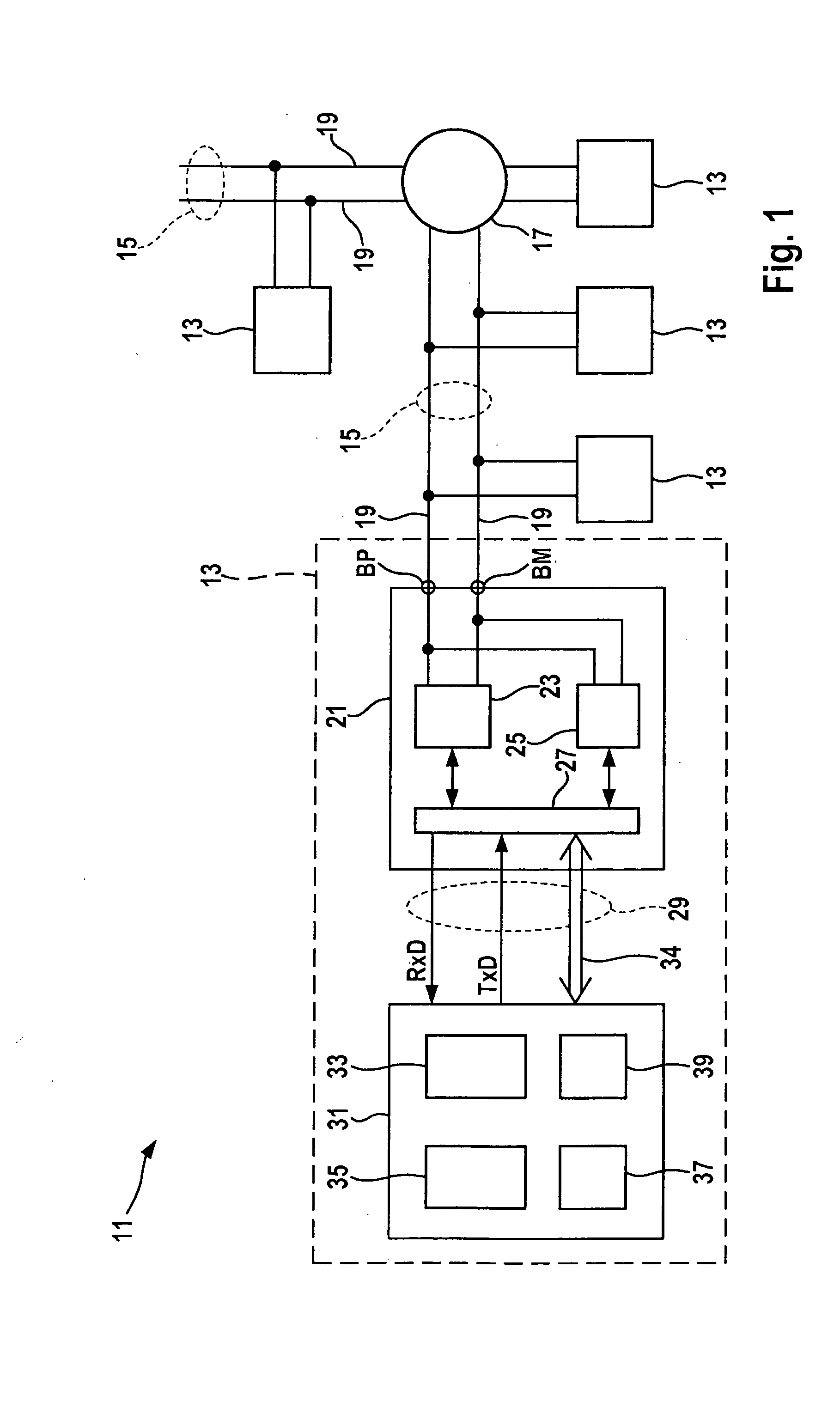
[0015]FIG. 1 shows a bus system 11, to which a plurality of nodes 13 is connected. Bus system 11 may be a FlexRay communication system and thus bus system 11 may be designed according to the specifications of the FlexRay Consortium.

[0016]Individual nodes 13 are interconnected via bus lines 15 either directly or indirectly via a star coupler 17. Each bus line 15 is designed to be a cable having at least one pair of leads composed of two leads 19, each forming an electrical conductor. Bus system 11 thus has one channel for transmission of data, this channel being formed by leads 19 of the pair of leads. In one specific embodiment (not shown), bus system 11 may have a plurality of channels, preferably two channels, which is embodied by two separate pairs of leads (not shown). Due to the use of two channels, the useful data rate of data transmissions among nodes 13 may be increased by transmitting different data over the two channels. Since the bus system is able to continue operating e...


PUM


Abstract

A circuit configuration for a node of a bus system includes a transceiver circuit and a control circuit connected to the transceiver circuit. The transceiver circuit has an idle mode, in which it has a reduced power consumption in comparison with at least one operating mode, and the transceiver circuit is supplied with power in the at least one operating mode via a power supply unit integrated into the transceiver circuit. The control circuit is connected to the power supply unit to supply the control circuit with power in the idle mode, and the circuit configuration has a controllable voltage regulator which is coupled to the transceiver circuit in such a way that the voltage regulator is deactivated in the idle mode to reduce the power consumption and activated in the operating mode to supply power to the transceiver circuit and the control circuit.

Description

BACKGROUND OF THE INVENTION[0001]1. Field of the Invention[0002]The present invention relates to a circuit configuration having a transceiver circuit and a bus system node having such a circuit configuration.[0003]2. Description of Related Art[0004]Control units, sensor systems and actuator systems in a motor vehicle or commercial vehicle in particular are often interconnected with the help of a communication system such as the bus system known by the FlexRay brand name. Communications traffic on the bus system, access mechanisms and receiving mechanisms, as well as error handling are regulated via a protocol. FlexRay is a fast, deterministic and error-tolerant bus system for use in motor vehicles in particular. The FlexRay protocol operates according to the principle of time division multiple access (TDMA), in which fixed time slots are assigned to subscribers and to the messages to be transmitted; during these time slots, the subscribers have exclusive access to the communications...

Claims


Application Information

Patent Timeline
Patent Type & Authority Applications(United States)
IPC IPC(8): G06F1/32
CPCH04L12/12H04L12/40032H04L12/40039Y02B60/34H04L2012/40273Y02B60/32H04L2012/40241Y02D30/50
Inventor NEUSCHELER, MARCOREGER, CHRISTIANERCKERT, RICARDOWENZLER, AXEL
Owner ROBERT BOSCH GMBH
Learn More