Circuit for conduit bender
- Summary
- Abstract
- Description
- Claims
- Application Information
AI Technical Summary
Benefits of technology
Problems solved by technology
Method used
Image

Examples
second embodiment
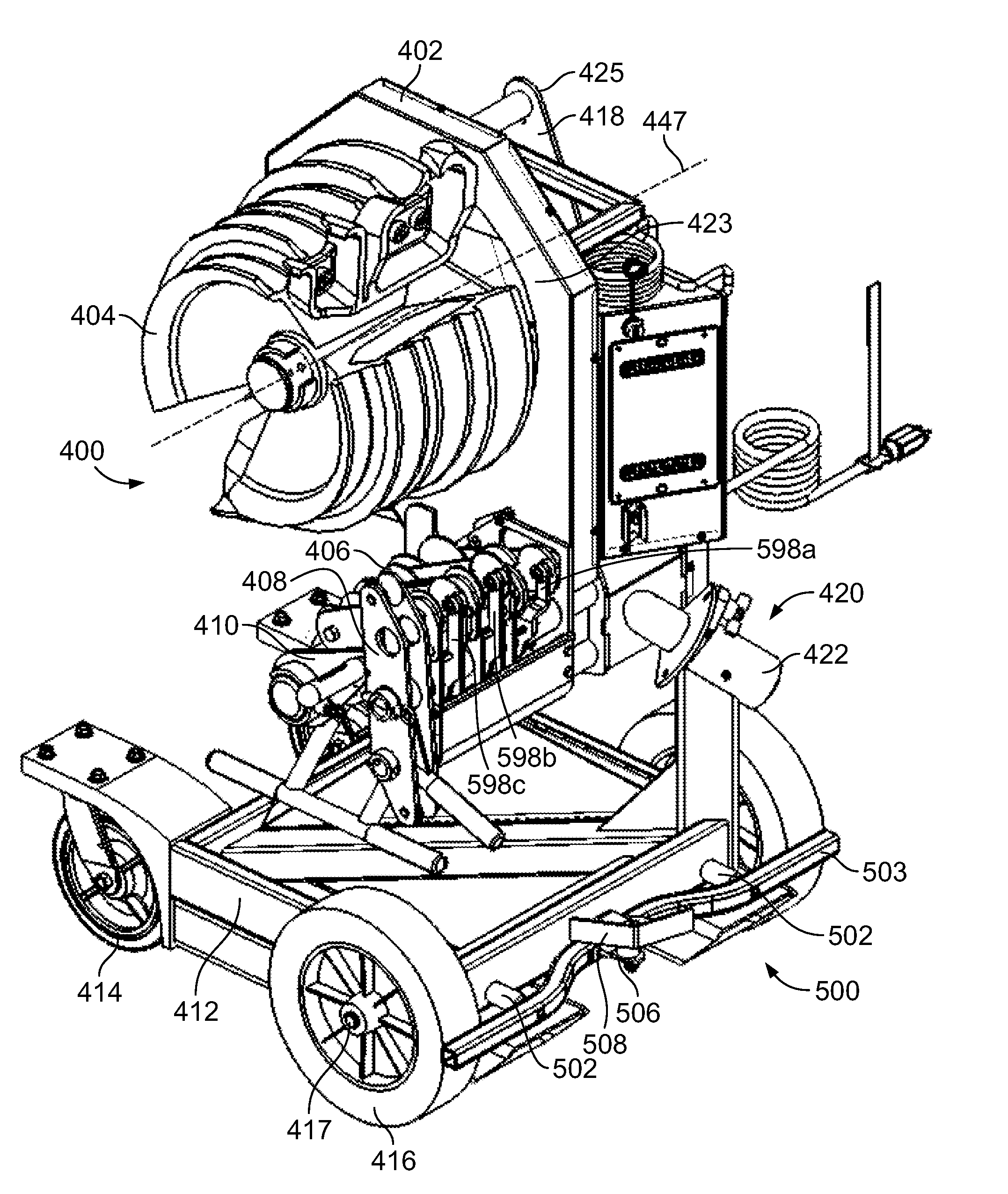
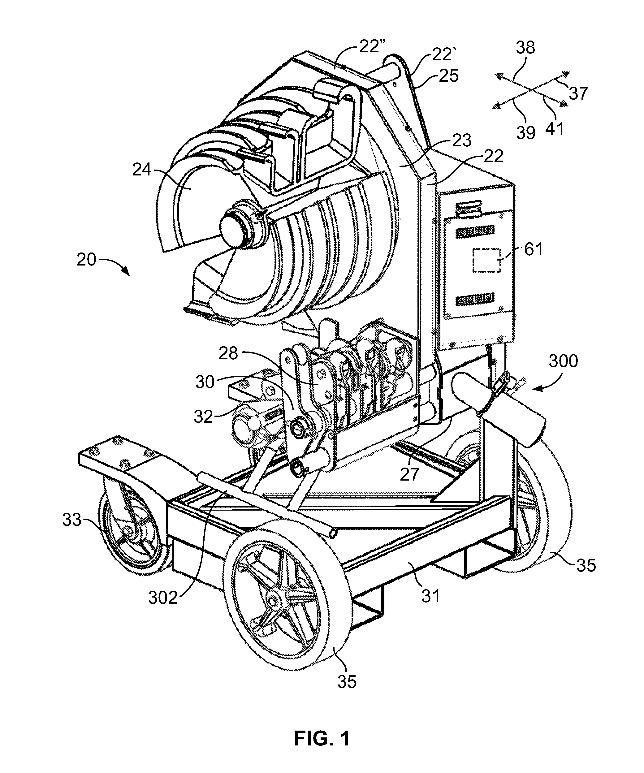
[0054]As shown, the conduit bender 20 is mounted to a base 31 which includes a pair of lead wheels 33 (one of which is shown in FIG. 1) and a pair of rear wheels 35 which are used to transport the conduit bender 20 from one location to the next. Of course, the conduit bender 20 is not required to be mounted to the moveable base 31. A braking assembly used to prevent rotation of the rear wheels 35 is described in connection with the conduit bender 400. It is to be understood that this braking mechanism can be utilized in connection with the base 31 as well.
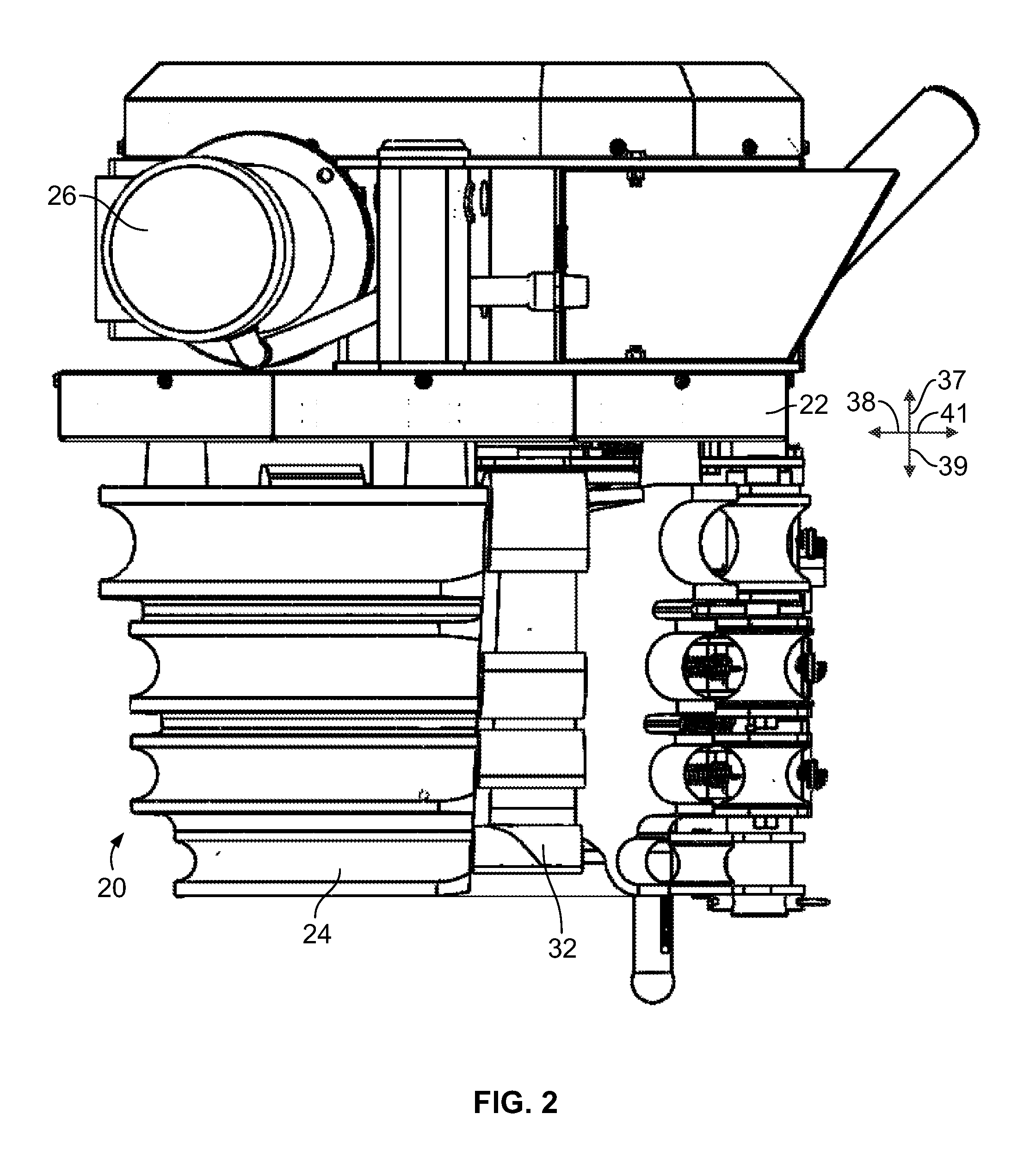
[0055]As will be described herein, the bender 20 is pivotally mounted to the base 20 and therefore can be pivoted between a vertical position as shown in FIG. 1 (i.e. a position in which the conduit is bent in a vertical plane) and a horizontal position (i.e. a position in which the conduit is bent in a horizontal plan “a e, a table-top” configuration). Thus, in describing the conduit bender 20, the terms “up” or “upper” and “down”...
first embodiment
[0159]The first lever assembly 598a includes a lever tube 600a and a lever 602a fixed thereto as best shown in FIG. 32, and a stop bar 606a. The lever tube 600a is cylindrically-shaped and defines an upper shaft passageway 607a. The lever 602a includes a lower gripping portion 608a, an intermediate elbow portion 610a, and an upper arm 612a portion. The lower gripping portion 608a includes first extension 614a and second extension 616a which extends around a portion of the outer surface of the lever tube 600a. The second extension 616a terminates in an end surface. An aperture 618a is provided proximate a lead end of the first extension 614a and a stop bar aperture is provided proximate the rear end of the first extension 614a. The elbow portion 610a extends between the lower portion 608a and the upper portion 612a and is generally S-shaped. The arm 612a of the lever 498a extends upwardly from the elbow portion 610a and includes a lower end 622a and an upper end 624a. An pair of roll...
PUM
| Property | Measurement | Unit |
|---|---|---|
| Size | aaaaa | aaaaa |
| Current | aaaaa | aaaaa |
| Electric potential / voltage | aaaaa | aaaaa |
Abstract
Description
Claims
Application Information
 - Generate Ideas
- Intellectual Property
- Life Sciences
- Materials
- Tech Scout
- Unparalleled Data Quality
- Higher Quality Content
- 60% Fewer Hallucinations
Browse by: Latest US Patents, China's latest patents, Technical Efficacy Thesaurus, Application Domain, Technology Topic, Popular Technical Reports.
© 2025 PatSnap. All rights reserved.Legal|Privacy policy|Modern Slavery Act Transparency Statement|Sitemap|About US| Contact US: help@patsnap.com