

Engine power compensation system of air vehicle
A technology of engine power and compensation system, applied in control/regulation system, non-electric variable control, flow control and other directions, can solve problems such as untimely adjustment, achieve the effects of improving accuracy, stable output voltage, and avoiding untimely adjustment
- Summary
- Abstract
- Description
- Claims
- Application Information
AI Technical Summary
Problems solved by technology
Method used
Image

Examples
Embodiment 1
[0017] Embodiment 1, an engine power compensation system of an air car, the input device transmits the gear position signal, the key signal, and the air flow signal to the ECU controller, and the ECU controller controls the air storage device to output air energy to drive the aerodynamic motor, Then drive the car to move forward. It is characterized in that the air dynamic motor also calculates the flow compensation signal through the logarithmic circuit. Compensate the output power of the aerodynamic motor;
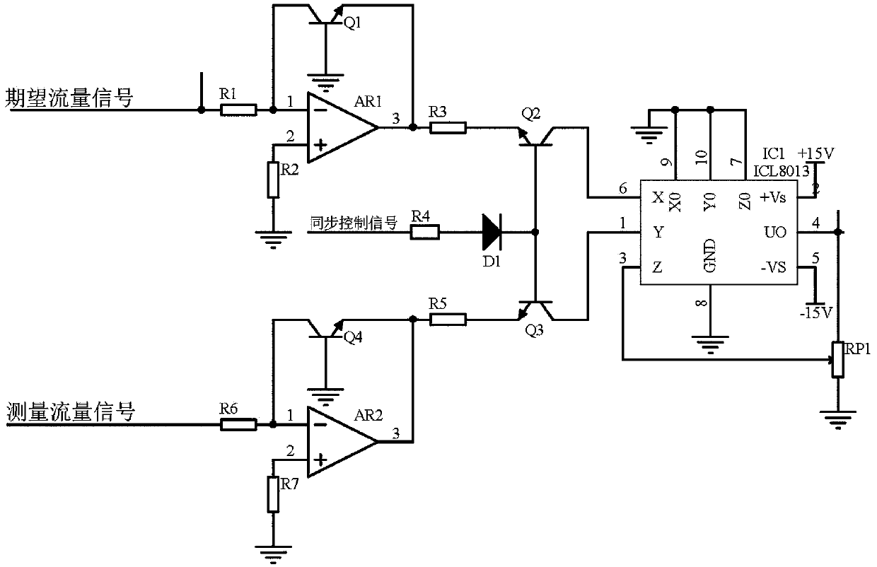
[0018] The logarithmic circuit receives the expected flow signal (given by the ECU) corresponding to the gear position signal and the key signal in the input device and the flow signal of the corresponding gear position signal and the key signal in the input device measured by the flow sensor entering the air-powered motor, Use the natural logarithmic operation circuit composed of operational amplifier AR1, resistor R1, resistor R2, and transistor Q1 to calculate the nat...
Embodiment 2
[0019] Embodiment 2, on the basis of Embodiment 1, the logarithmic circuit receives the gear position signal in the input device, the expected flow signal corresponding to the key signal, and the corresponding gear position signal in the input device measured by the flow sensor, and the key signal enters the air. For the flow signal of the power motor, use the natural logarithm operation circuit composed of operational amplifier AR1, resistor R1, resistor R2, and transistor Q1 to calculate the natural logarithm operation of the expected flow signal received, that is, calculate the ln expected flow signal, and use the operational amplifier The natural logarithmic operation circuit composed of AR2, resistor R6, resistor R7, and triode Q4 calculates the natural logarithm operation for the measured flow signal, that is, calculates the ln measured flow signal, and under the control of the switch composed of triode Q3 and Q2, simultaneously backward Level circuit transmission, specif...
Embodiment 3
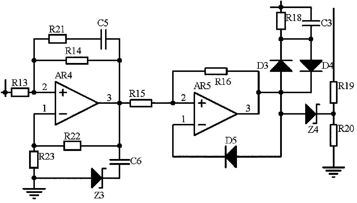
[0020] Embodiment 3, on the basis of Embodiment 2, the signal coupling circuit receives the flow compensation signal, and the proportional amplification circuit with feedback with the operational amplifier AR4 as the core performs proportional adjustment and converts it into a signal for driving the flow valve, specifically an operational amplifier The amplifying circuit composed of AR4, resistor R13, resistor R4, resistor R21, resistor R23, capacitor C5, capacitor C6 in series and voltage regulator tube Z3 is proportionally amplified and then transmitted backwards. At the same time, when the voltage at the output terminal of the operational amplifier AR4 changes slightly Hours, the capacitor C6 is equivalent to disconnection, the proportionally amplified signal is fed back to the inverting input terminal of the operational amplifier AR4 through the resistor R22, the same / inverting input terminal of the operational amplifier AR4 is compared, and the output 0 signal is transmitte...
PUM
 Abstract
Description
Claims
Application Information