Liquid droplet discharging apparatus

Active Publication Date: 2011-09-01
KATEEVA
View PDF9 Cites 3 Cited by
  • Summary
  • Abstract
  • Description
  • Claims
  • Application Information

AI Technical Summary

Benefits of technology

[0019]With this constituent features, the discharge function of the functional liquid drople

Problems solved by technology

With this kind of liquid droplet discharging apparatus, although the workpiece processing cycle time can be shortened by exchanging workpieces with respect to one workpiece stage while forming an image on a workpiece carried on th

Method used


Image

  • Liquid droplet discharging apparatus
  • Liquid droplet discharging apparatus
  • Liquid droplet discharging apparatus

Examples


Example

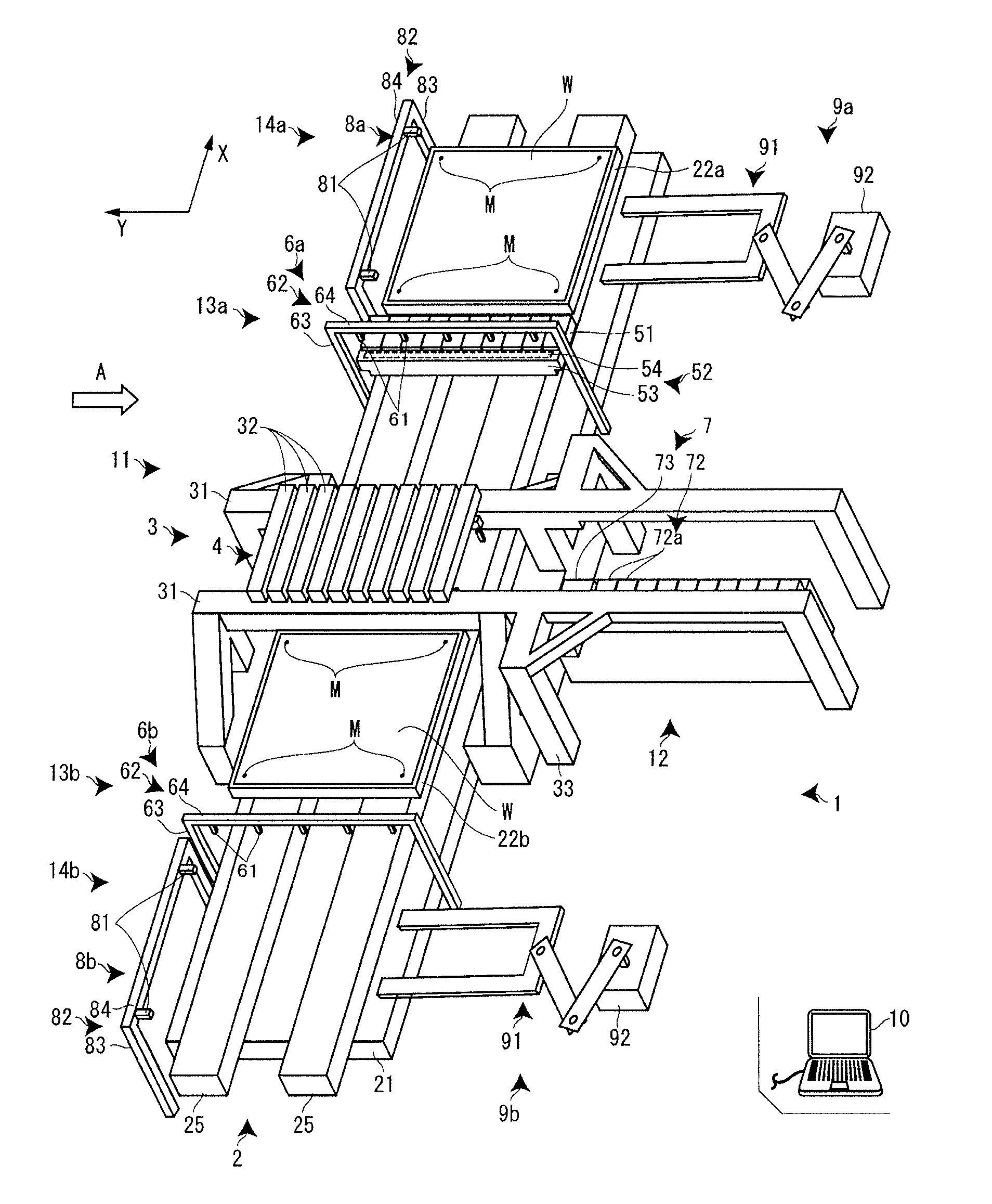
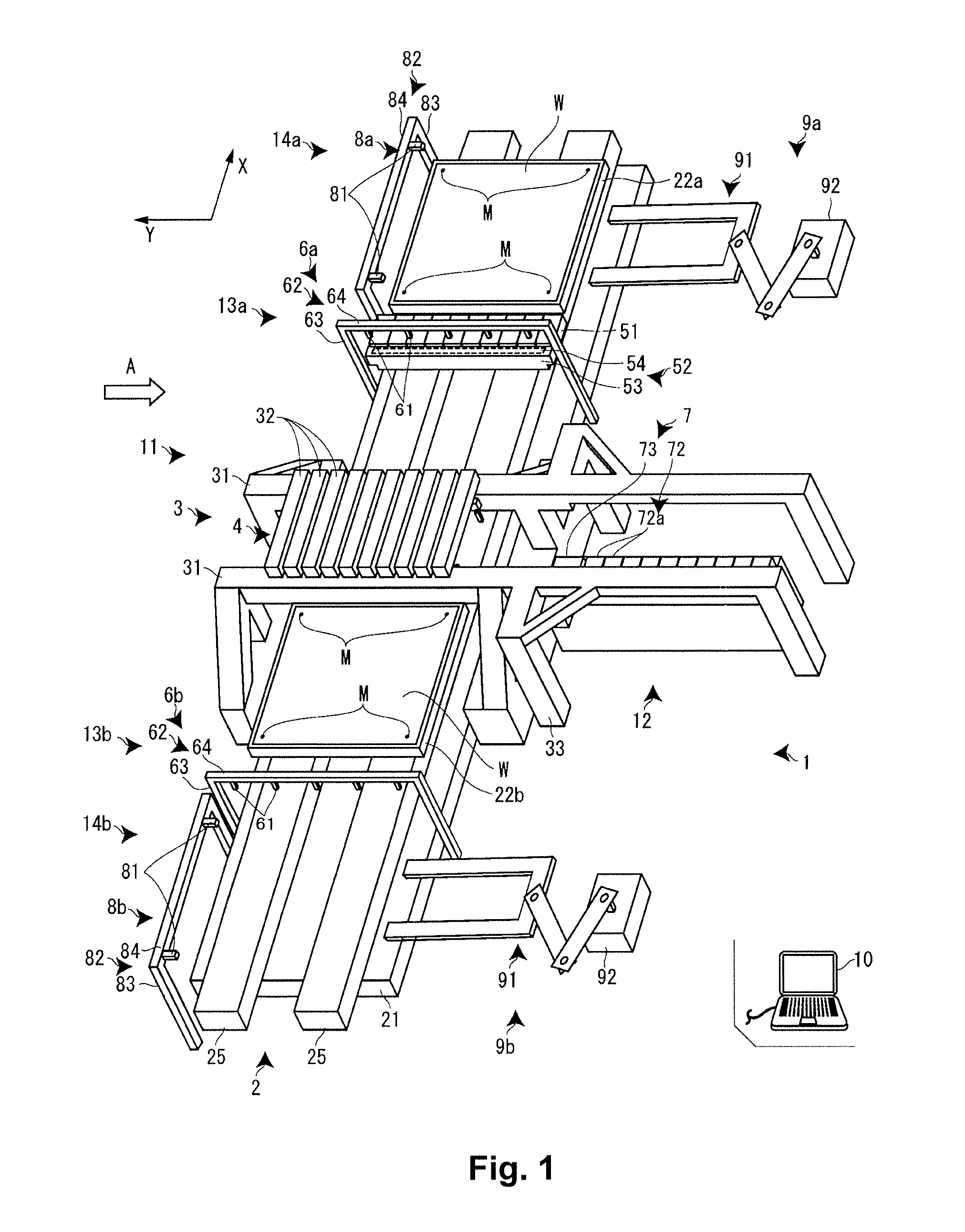
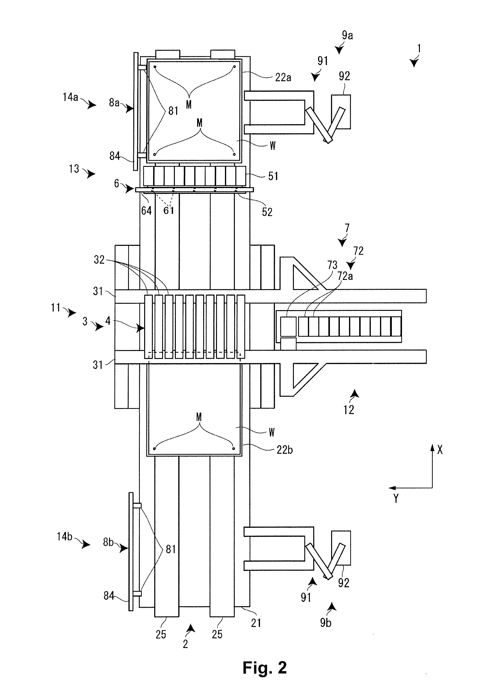
[0030]A liquid droplet discharging apparatus according to an embodiment of the present invention will now be explained with reference to the appended drawings. This liquid droplet discharging apparatus is intended to be installed in a manufacturing line for flat panel displays and uses a functional liquid droplet discharging head supplied with a functional liquid—e.g., a special ink or a liquid resin having a light emitting property—to form (image formation) a color filter of a liquid crystal display device or light emitting elements serving as pixels of an organic EL device.

[0031]As shown in FIGS. 1 to 3, the liquid droplet discharging apparatus 1 includes the following: an X axis table 2 (stage moving mechanism) that is arranged on an X axis support base 21 supported on a base such as a granite surface plate, extends in an X axis direction serving as a main scanning direction, and configured to move a workpiece W along the X axis direction; a Y axis table 3 that extends in a Y axi...


PUM


Abstract

A liquid droplet discharging apparatus includes a pair of workpiece stages, a workpiece moving table configured to move the two workpiece stages, a head moving table configured to move a functional liquid droplet discharging head, a pair of workpiece exchanging mechanisms arranged in two workpiece exchange areas, and a control unit. The control unit is configured to execute control to move the workpiece stages alternately between the image formation area and the workpiece exchange areas such that one of the workpiece stages moves between the image formation area and one of the workpiece exchange areas and the other of the workpiece stages moves between the image formation area and the other of the workpiece exchange areas. Furthermore, the control unit executes control such that image forming operations and exchanges of workpieces are executed alternately with respect each of the workpiece stages.

Description

CROSS-REFERENCE TO RELATED APPLICATIONS[0001]This application claims priority to Japanese Patent Application No. 2010-043797 filed on Mar. 1, 2010. The entire disclosure of Japanese Patent Application No. 2010-043797 is hereby incorporated herein by reference.BACKGROUND[0002]1. Technical Field[0003]The present invention relates to a liquid droplet discharging apparatus having a pair of workpiece tables and configured to alternately form images on workpieces mounted on the workpiece tables and execute exchanges of workpieces with respect to the workpiece tables.[0004]2. Related Art[0005]A known example of this kind of liquid droplet discharging apparatus has a pair of workpiece stages arranged in a stationary manner and a head moving mechanism having a line-type functional liquid droplet discharging head mounted thereon and configured to move the functional liquid droplet discharging head between a pair of image forming stages. The liquid droplet discharging apparatus forms an image ...

Claims


Application Information

Patent Timeline
IPC IPC(8): B41J29/38B41J2/01
CPCB41J3/28H01L27/1292B41J11/06B41J3/407
Inventor KOJIMA, KENJI
Owner KATEEVA
Why Eureka
Try Eureka