Electric power steering device

a technology of electric power steering and steering coil, which is applied in the direction of electrical steering, electric motor control, transportation and packaging, etc., can solve the problems of large electric power consumption, and achieve the effect of preventing the hysteresis loss of the boosting coil and increasing the electric power supply ability of the sub-batteries

Inactive Publication Date: 2011-11-10
TOYOTA JIDOSHA KK
View PDF7 Cites 27 Cited by
  • Summary
  • Abstract
  • Description
  • Claims
  • Application Information

AI Technical Summary

Benefits of technology

[0004]The object of the present invention is to solve the above-mentioned problems and to prevent overheat of the coil of the booster circuit.
[0009]As a result, according to the present invention, overheat of the booster circuit can be prevented.
[0013]It should be noted that for example, even by using an electric current sensor, due to an effect of measurement noises thereof, no backward electric current flowing in the booster circuit can be successively detected. On the other hand, according to the present invention, the possibility that a backward electric current flows, is estimated by the steering condition, and therefore overheat of the booster circuit can be appropriately prevented.
[0015]According to the present invention, an electric energy is generated by switching the first switching element on and off in a short cycle to intermittently flow an electric current in the boosting coil. The electric energy is discharged to the power supply channel leading to the motor drive circuit by switching the second switching element on. The electric power having a voltage resulted by boosting the output voltage of the vehicle battery device is supplied to the motor drive circuit by the above-explained switching operation. In this case, it can be estimated if there is a possibility that a backward electric current flows in the boosting coil on the basis of the input and output voltages of the booster circuit and single switch-on and switch-off periods of the first switching element. According to the present invention, the voltage information acquisition means acquires information on input and output voltages of the booster circuit, and the switching information acquisition means acquires switching information indicating single switch-on and switch-off periods of the first switching element. Then, it is estimated if there is a possibility that a backward electric current flows on the basis of the acquired information. For example, when a value [(T1+T2)×v1−(T2×v2)] obtained by subtracting a value (T2×v2) obtained by multiplying the switch-off period T2 by the output voltage v2 from a value (T1+2)×v1 obtained by multiplying the sum (T1+T2) of the single switch-on and switch-off periods T1 and T2 of the first switching element by the input voltage v1, is negative, it can be estimated that a backward electric current flows. As a result, according to the present invention, overheat of the booster circuit can be prevented.
[0019]According to the present invention, when the boosting operation of the booster circuit is stopped, no backward electric current flows in the booster circuit via the second switching element by maintaining the both of the first and second switching elements in the switch-off condition. Accordingly, the generation of a backward electric current can be surely prevented.
[0022]According to the present invention, when the electric power supply ability of the sub battery device is below a prescribed value and it is estimated that there is a possibility that a backward electric current flows, in place of the stopping of the boosting operation, the boosting is controlled such that the output voltage of the booster circuit is maintained at a voltage higher than the output voltage of the sub battery device. Thereby, an electric current which is generated in the electric motor and a surplus electric current which cannot be consumed by the electric motor flow to the sub battery device, which is in the low voltage condition, as a charging electric current. Accordingly, no backward electric current flows in the booster circuit, and therefore overheat due to a hysteresis loss of the boosting coil can be prevented. Further, the electric power supply ability of the sub battery device can be increased.

Problems solved by technology

Such an electric power steering device is powered by a vehicle battery for supplying an electric power to general vehicle electric loads, and the consumption of the electric power is large.

Method used


Image

  • Electric power steering device
  • Electric power steering device
  • Electric power steering device

Examples


Embodiment Construction

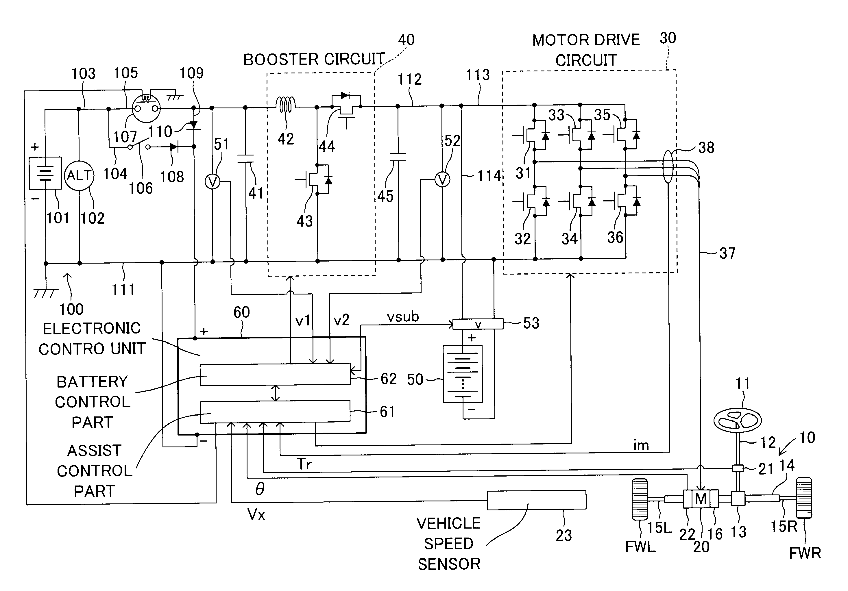
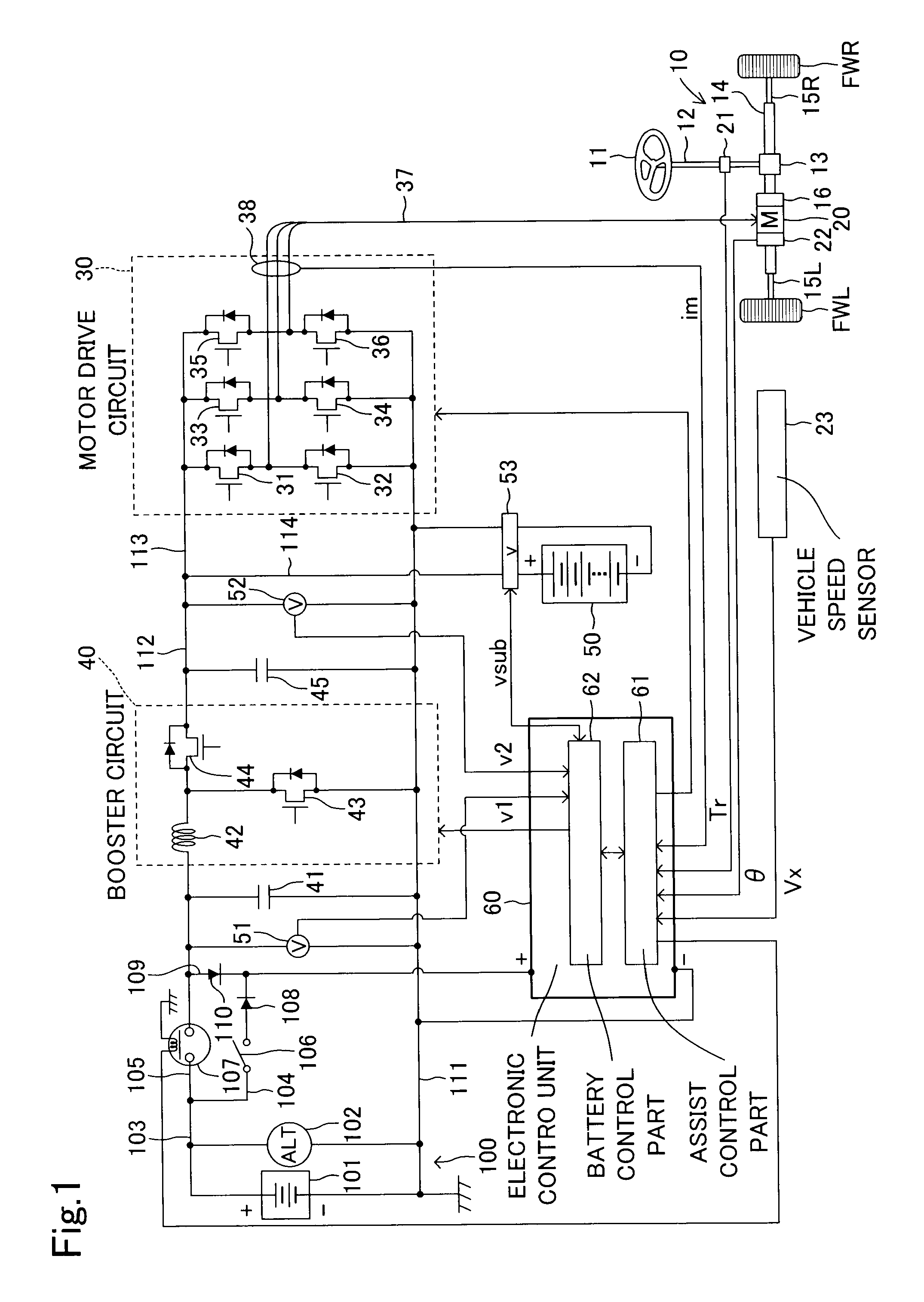
[0036]Below, an electric power steering device of an embodiment according to the invention will be explained, referring to the drawings. FIG. 1 is a schematic configuration view of an electric power steering device for a vehicle of the embodiment.

[0037]The electric power steering device comprises, as a main part, a steering mechanism 10 for turning wheels to be turned by a steering operation of a steering wheel 11, an electric motor 20 assembled to the steering mechanism 10 for generating a steering assist torque, a motor drive circuit 30 for driving the electric motor 20, a booster circuit 40 for boosting a voltage of an electric power output from a vehicle battery device 100 and supplying the electric power to the motor drive circuit 30, a sub battery device 50 connected to an electric power supply circuit positioned between the booster circuit 40 and the motor drive circuit 30 in parallel to the electric power supply circuit, and an electronic control unit 60 for controlling oper...


PUM


Abstract

An electric power steering device for a vehicle includes an estimation mechanism estimating if there is a possibility that a backward electric current flows in a booster circuit toward a vehicle battery device, and a boosting controller stopping the boosting operation of the booster circuit to prevent a backward electric current from flowing in the booster circuit when it is estimated that there is a possibility that a backward electric current flows by the estimation mechanism. The estimation mechanism estimates that there is a possibility that a backward electric current flows in the booster circuit when the steering condition of a steering wheel is a returning condition or a steering-held condition. Otherwise, the estimation mechanism estimates if a backward electric current flows on the basis of input and output voltages of the booster circuit and information on the switching of a first boosting switching element. Thereby, overheat of the booster circuit can be prevented.

Description

TECHNICAL FIELD[0001]The present invention relates to an electric power steering device provided with an electric motor for applying a steering assist torque to a steering mechanism.BACKGROUND ART[0002]Conventionally, for example, in an electric power steering device, an electric motor is provided for applying a steering assist torque to a steering mechanism, and a steering operation by a driver is assisted by controlling energization of the electric motor. Such an electric power steering device is powered by a vehicle battery for supplying an electric power to general vehicle electric loads, and the consumption of the electric power is large. Accordingly, for example, in a device proposed in the Unexamined Japanese Patent Publication No. 2007-91122, a sub battery device is provided for assisting the vehicle battery. The sub battery device is constituted such that it is connected to a power supply line in parallel thereto from the vehicle battery to a motor drive circuit and is char...

Claims


Application Information

Patent Timeline
Patent Type & Authority Applications(United States)
IPC IPC(8): B62D5/04B62D6/00B62D6/02B62D113/00B62D119/00
CPCB62D5/046B62D5/0466B62D5/0481H02P29/024H02P29/00H02P29/0055H02M1/32H02P29/0241H02P29/64H02P29/40H02P29/50
Inventor FUJIMOTO, MASAKIYAMASHITA, MASAHARUAOKI, KENICHIRONISHIKOHRI, MEGUMUOHTOMO, AKIHIROKASAI, EIJIONAGI, TSUTOMUNIKI, KEITARO
Owner TOYOTA JIDOSHA KK
Why Eureka
Try Eureka