Electronic reading system

a reading system and electronic technology, applied in the field of electronic reading systems, can solve the problems of not being able to successfully implement the idea, the way information is presented and delivered by the printed material is rather limited, and the idea is still far from satisfactory, so as to achieve the effect of reducing dimension and weight, and reducing learning difficulty and cost for the blind

Inactive Publication Date: 2011-11-10
YAU YIMWAI
View PDF20 Cites 0 Cited by
  • Summary
  • Abstract
  • Description
  • Claims
  • Application Information

AI Technical Summary

Benefits of technology

[0022]A major objective of the present invention is to effectively integrate printed books and electronic reading devices.
[0028]The photoelectric device contains an infrared transmitter, a camera, a photoelectric conversion circuit, and a radio circuit, all housed in a hollow object. The hollow object is mainly composed of a front portion and a back portion. The front portion has a front opening through which the infrared light from the infrared transmitter is radiated. The camera picks up a reflected image also through the front opening. The back portion contains an output circuit which is electrically connected to the processor board or IC card. The radio circuit is electrically connected to a shielding mechanism preventing inductance interference.
[0029]Alternatively, the hollow object could be composed of a front portion, a middle portion, and a back portion. The middle portion has a hollow space for accommodating the front portion. The back portion contains a telescoping section and an operation section. The middle section is housed in the telescoping section. The operation section accommodates a built-in battery and an output circuit with a second radio circuit. The radio circuit is electrically connected to a shielding mechanism preventing inductance interference.
[0034]The gist of the present invention lies in the novel integration of printed books and electronic reading devices. The printed books could still be read in an ordinary manner while, together with the electronic reading device, a richer reading experience could be achieved.
[0040]The present invention is cable of solving the reading problem for the blind by providing synchronous pronunciation. The books for the blind could thereby have a reduced dimension and weight. The learning difficulty and cost for the blind is therefore significantly reduced. The blind could learn and work with greater efficiency, helping them to participate social life more effectively.

Problems solved by technology

Yet, the ways information is presented and delivered by the printed material are rather limited.
However, this idea has not yet been successfully implemented.
Even though various manufacturers have been continuously pushing new solutions and products into the market, the result is still far from satisfactory.
It seems that the printed material cannot be entirely replaced and that conventional publication industry could not treat the digital revolution lightly.
The main problem is that the disks and cards are required additional device and separate process to gain the additional benefit.
However, strict printing condition has to be followed and content editing requires professionals.
Theoretically it should be feasible, but it is not a practical solution.
For a book, there are too numerous elements and it is not practical to associate a tag for each of them.
However, this would be a challenge to the blind.
This would be even more challenging to the blind.
On the other hand, the radio circuit cannot radiate too strong or too weak a radio signal.
If the radio signal is too strong, there is a high probability of misjudgement of the touched point.
If the radio signal is too weak, it cannot penetrated a thick book and cannot be picked up by the electronic coordinate circuit.
These teachings, despite their usefulness, still have limited application and some restriction.

Method used


Image

  • Electronic reading system
  • Electronic reading system
  • Electronic reading system

Examples


Embodiment Construction

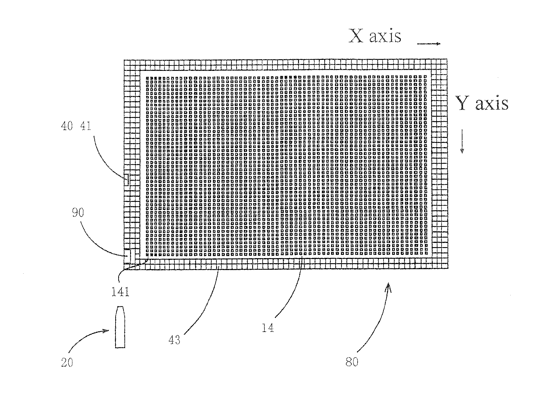
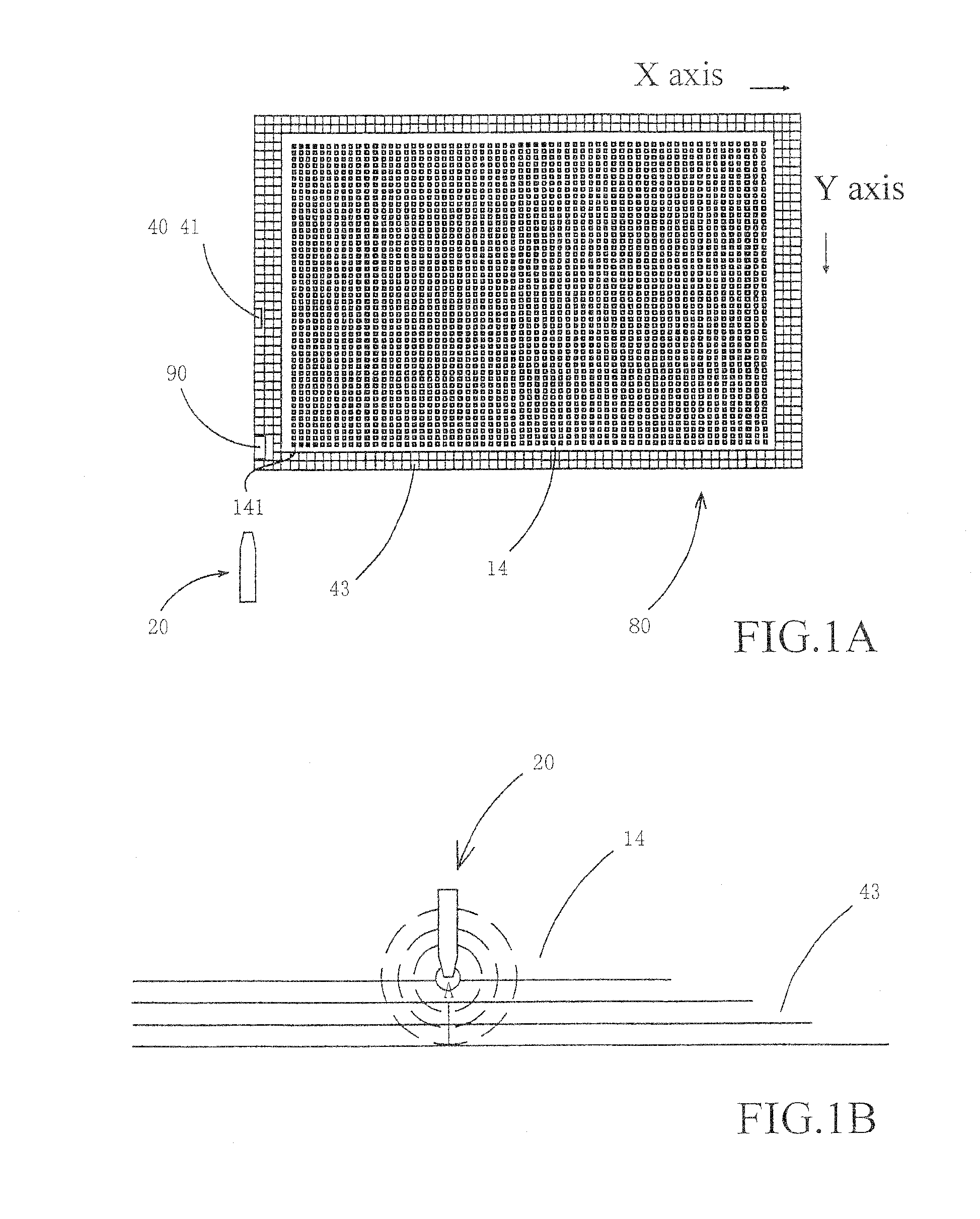
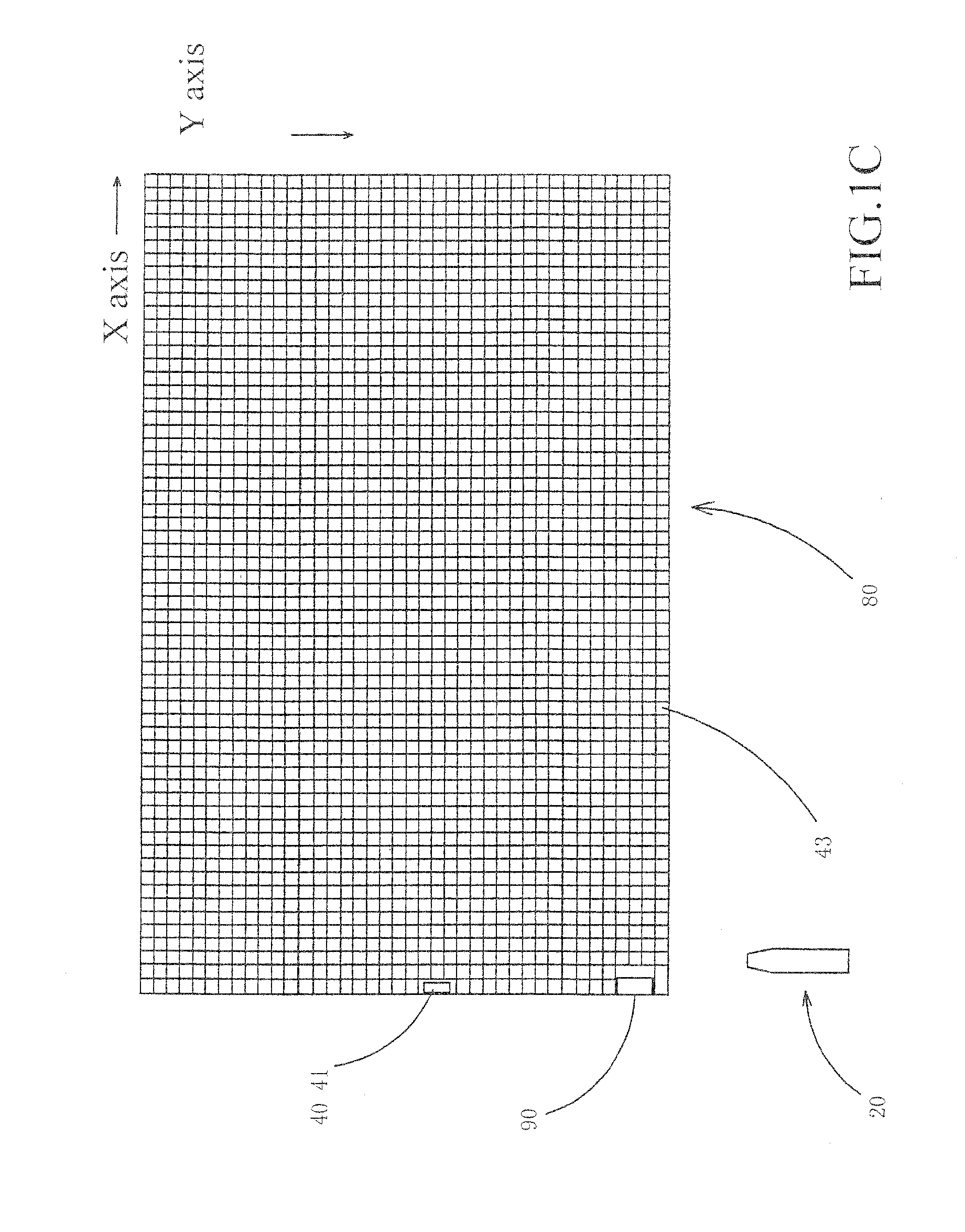
[0059]The following descriptions are exemplary embodiments only, and are not intended to limit the scope, applicability or configuration of the invention in any way. Rather, the following description provides a convenient illustration for implementing exemplary embodiments of the invention. Various changes to the described embodiments may be made in the function and arrangement of the elements described without departing from the scope of the invention as set forth in the appended claims.

[0060]According an embodiment of the present invention, the photoelectric device 22 contains an infrared transmitter 221, a camera 222, and a photoelectric conversion circuit 223. The data page 14 has data carrier configured on its surface. The electronic reading device contains a grid antenna circuit board 43, a radio circuit 21 transmitting signal of a specific frequency, a processor board 40 with a built-in storage or an IC card 41. The processor board 40 or IC card 41 is capable of converting da...


PUM


Abstract

The present invention integrates printed books with electronic reading devices. The present invention contains a photoelectric device, at least a data page, and an electronic reading device. The photoelectric device contains an infrared transmitter, a camera, and a photoelectric conversion circuit. The data page has data carrier configured on its surface. The electronic reading device contains a grid antenna circuit board, a radio circuit transmitting signal of a specific frequency, a processor board with a built-in storage or an IC card. The processor board or IC card is capable of converting data retrieved by the photoelectric device into corresponding electronic data so that the content of the electronic data could be read by connected electronic reading device or external card reader.

Description

TECHNICAL FIELD OF THE INVENTION[0001]The present invention is generally related to the integration of printed books and electronic devices, and more particularly to an electronic reading system capable of detecting invisible codes printed on the book pages.DESCRIPTION OF THE PRIOR ART[0002]Various printed documents and material are an essential part of our daily life. Yet, the ways information is presented and delivered by the printed material are rather limited.[0003]Following the advancement of the digital and communication technologies, various media for information delivery are invented, such as the electronic books, learning machines, PDAs.[0004]In the education arena, therefore there is a paperless idea which is intended to reduce children's burden by digitizing and storing printed textbooks a hand-held electronic reading device or a tablet computer. However, this idea has not yet been successfully implemented.[0005]Even though various manufacturers have been continuously pus...

Claims


Application Information

Patent Timeline
Patent Type & Authority Applications(United States)
IPC IPC(8): G06K7/01G06K7/12
CPCB42D1/007G09B5/062B42D3/12
Inventor YAU, YIMWAI
Owner YAU YIMWAI
Why Eureka
Try Eureka