Low breakout friction energized gasket

Inactive Publication Date: 2011-11-10
FLOWSERVE MANAGEMENT CO
View PDF2 Cites 20 Cited by
  • Summary
  • Abstract
  • Description
  • Claims
  • Application Information

AI Technical Summary

Benefits of technology

[0016]The gasket of the invention has special features which prove beneficial to applications in face type mechanical seals. In these seals, the seal rings can be made from very hard materials such as tungsten or silicon carbide, or softer materials such as mechanical grade carbon.

Problems solved by technology

However, tests have proven that as hydraulic pressure increases, the forces transmitted through the inner cup walls in contact with the abutting sealing surfaces increases.
Attempts to reduce sealing lip forces by relieving part of the gasket lip sealing surface and adding a support heal is less effective as pressures increase the deformation of the gasket.
As such, the application of these designs to mechanical seals for other than a static seal can pose critical problems.
Using these known cup designs for a flexible rotating or stationary seal ring in a mechanical seal application can be problematic relative to maintaining seal face flatness and free axial movement of the seal ring relative to the seal sleeve.
This force has

Method used


Image

  • Low breakout friction energized gasket
  • Low breakout friction energized gasket
  • Low breakout friction energized gasket

Examples


Embodiment Construction

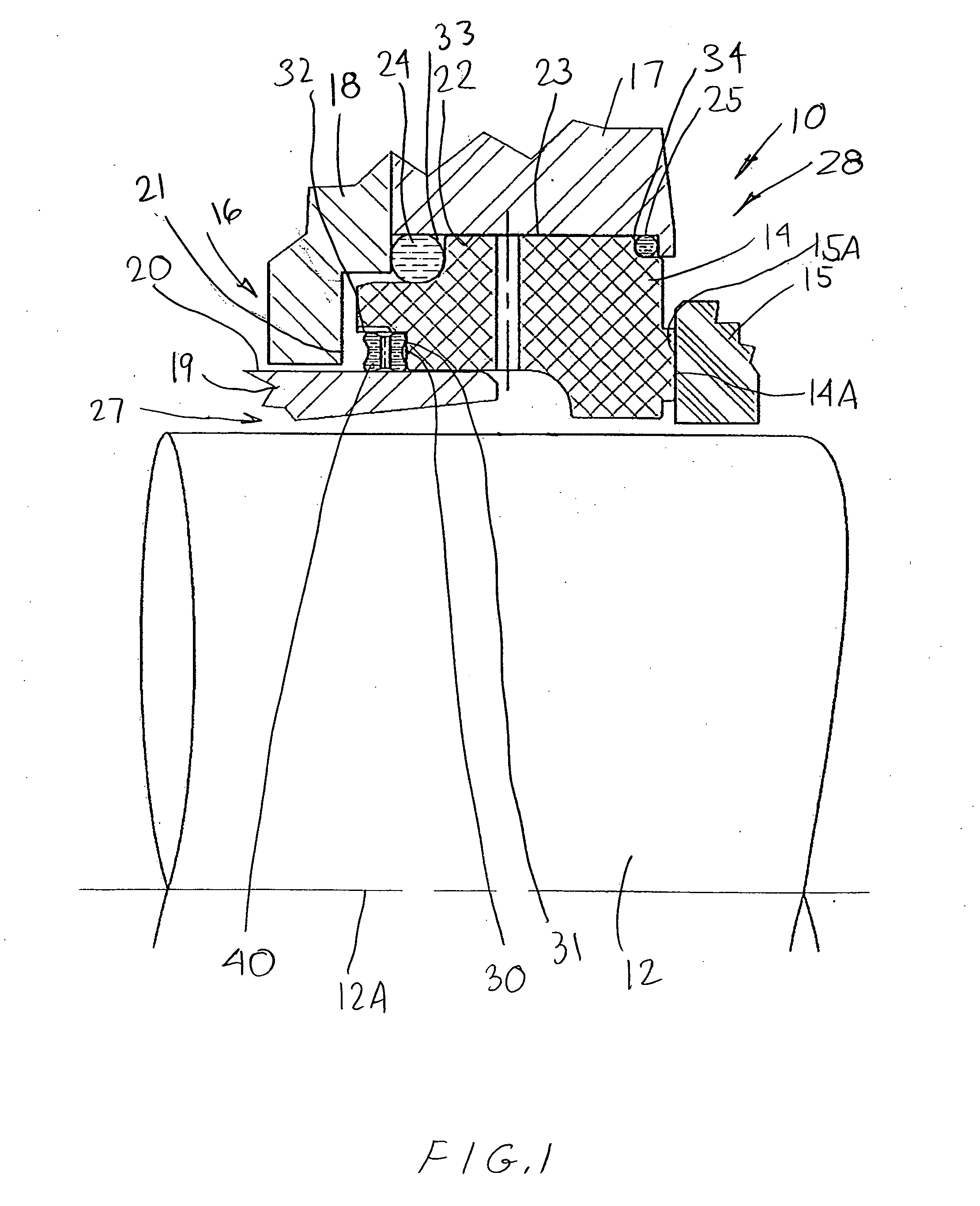
[0029]Referring to FIG. 1, a conventional mechanical seal assembly 10 is shown mounted to a rotatable shaft 12. As described hereinafter, the invention relates to a gasket construction for use with various types of known mechanical seals including the seal 10 illustrated in FIG. 1 as well as other mechanical seals.

[0030]More particularly as to the mechanical seal construction, the mechanical seal 10 includes various seal components of different types and constructions which are assembled together to define the seal assembly. In this regard, the seal components of the mechanical seal 10 comprises a pair of relatively rotatable seal rings 14 and 15 wherein the seal ring 15 preferably is mounted to the shaft such as by a shaft sleeve or the other like component so that the seal ring 15 rotates in unison with the shaft 12. The mating seal ring 14 preferably is stationarily mounted to a housing assembly 16 which comprises a first housing component 17, a second housing component 18 dispos...


PUM


Abstract

A mechanical seal typically includes gaskets as secondary seals therein. An improved gasket is provided which has a U cup design wherein the gasket is formed with a first spring-energized groove which opens radially and has a deflectable sealing wall which is deflectable axially, and includes a second spring-energized groove which is canted at an angle relative to the axial and radial directions wherein the groove defines a sealing leg which is deflectable at an angle relative to the axial and radial directions. A support ring supports the canted sealing leg along the major extent thereof wherein an end portion of the canted sealing leg is disposed for sealing contact with an axially-extending component surface.

Description

FIELD OF THE INVENTION[0001]The invention relates to a mechanical seal and a secondary seal therefor, and more particularly, to an energized gasket having a low breakout friction.BACKGROUND OF THE INVENTION[0002]Mechanical face seals are used on various types of machines and equipment, such as pumps, compressors, and turbines which have a rotating shaft and a sealing chamber adjacent the shaft wherein the mechanical seal prevents leakage of fluid from the sealing chamber. Many such mechanical seals include a pair of adjacent seal rings which have opposing seal faces that define a sealing region therebetween to sealingly separate the sealing chamber from an exterior region. Typically, one of the seal rings is mounted on the shaft so as to rotate therewith while the other stationary seal ring is non-rotatably mounted on a seal housing. Also, at least one of the rotating and stationary seal rings is axially movable. To maintain a seal between the opposed seal faces, the axially movable...

Claims


Application Information

Patent Timeline
IPC IPC(8): F16J15/38
CPCF16J15/166F16J15/3212F16J15/441F16J15/3236F16J15/322
Inventor GRACE, RONALD L.YOUNG, LIONEL A.
Owner FLOWSERVE MANAGEMENT CO
Why Eureka
Try Eureka