Method for Determining Inverse Filter from Critically Banded Impulse Response Data

a technology of impulse response data and inverse filter, which is applied in the direction of frequency response correction, signal processing, electrical equipment, etc., can solve the problems of severe distortion in a fully inverse filter system, and achieve the effect of efficiently performing inverse filter determination and minimizing the expression of mean square error

Active Publication Date: 2011-11-10
DOLBY LAB LICENSING CORP +1
View PDF3 Cites 18 Cited by
  • Summary
  • Abstract
  • Description
  • Claims
  • Application Information

AI Technical Summary

Benefits of technology

[0015]Nor had it been known until the present invention how to perform inverse filter determination efficiently, including by applying eigenfilter theory (e.g., including by expressing stop band and pass band errors as Rayleigh quotients), or by minimizing a mean square error expression by solving a linear equation system.

Problems solved by technology

Noise or small inaccuracies in the impulse response measurement may then result in severe distortion in a fully inverse filtered system.

Method used


Image

  • Method for Determining Inverse Filter from Critically Banded Impulse Response Data
  • Method for Determining Inverse Filter from Critically Banded Impulse Response Data
  • Method for Determining Inverse Filter from Critically Banded Impulse Response Data

Examples


Embodiment Construction

[0051]Many embodiments of the present invention are technologically possible. It will be apparent to those of ordinary skill in the art from the present disclosure how to implement them. Embodiments of the inventive system, method, and medium will be described with reference to FIGS. 1-9.

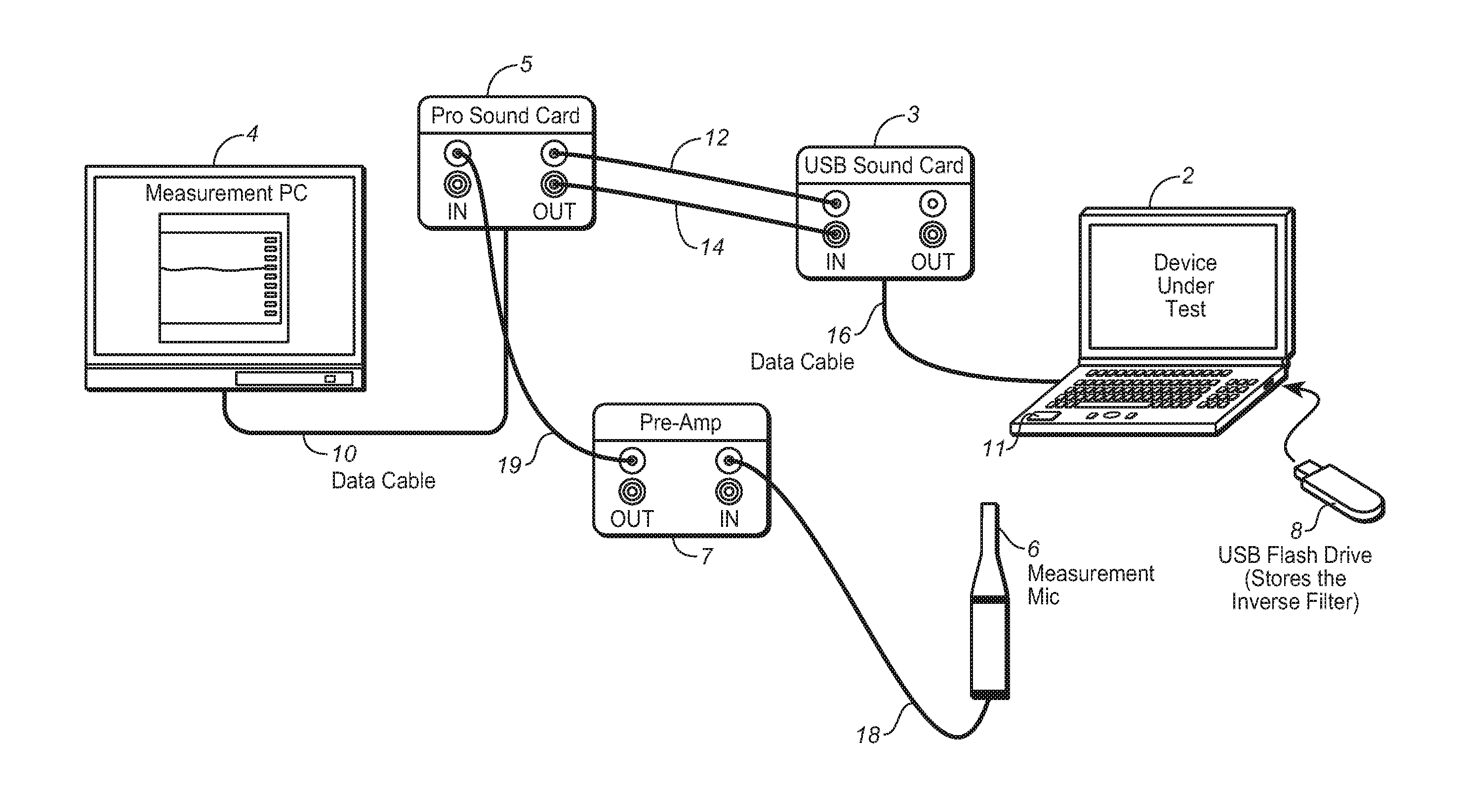
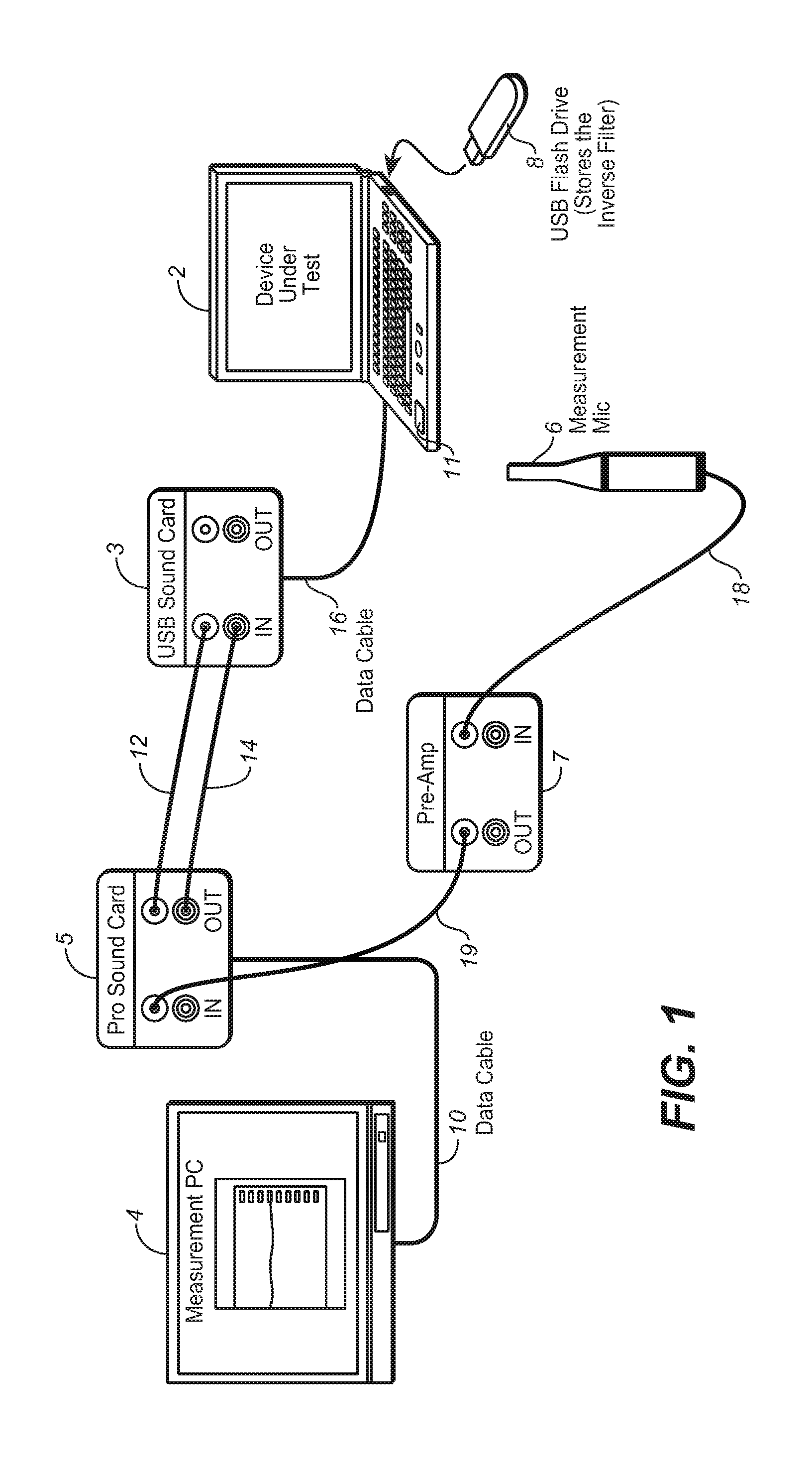
[0052]FIG. 1 is a schematic diagram of an embodiment of a system for determining an inverse filter in accordance with the invention. The FIG. 1 system includes computers 2 and 4, sound card 5 (coupled to computer 4 by data cable 10), sound card 3 (coupled to computer 2 by data cable 16), audio cables 12 and 14 coupled between outputs of sound card 5 and inputs of sound card 3, microphone 6, preamplifier (preamp) 7, audio cable 18 (coupled between microphone 6 and an input of preamp 7), and audio cable 19 (coupled between an output of preamp 7 and an input of sound card 5). In typical embodiments, the system can be operated to measure the impulse response of a loudspeaker (e.g., loudspeaker 11 of com...


PUM


Abstract

A method for determining an inverse filter for altering the frequency response of a loudspeaker so that with the inverse filter applied in the loudspeaker's signal path the inverse-filtered loudspeaker output has a target frequency response, and optionally also applying the inverse filter in the signal path, and a system configured (e.g., a general or special purpose processor programmed and configured) to determine an inverse filter. In some embodiments, the inverse filter corrects the magnitude of the loudspeaker's output. In other embodiments, the inverse filter corrects both the magnitude and phase of the loudspeaker's output. In some embodiments, the inverse filter is determined in the frequency domain by applying eigenfilter theory or minimizing a mean square error expression by solving a linear equation system.

Description

CROSS-REFERENCE TO RELATED APPLICATIONS[0001]This application claims priority to U.S. Patent Provisional Application No. 61 / 148,565, filed 30 Jan. 2009, hereby incorporated by reference in its entirety.BACKGROUND OF THE INVENTION[0002]1. Field of the Invention[0003]The invention relates to methods and systems for determining an inverse filter for altering a loudspeaker's frequency response in an effort to match the output of the inverse-filtered loudspeaker to a target frequency response. In typical embodiments, the invention is a method for determining such an inverse filter from measured, critically banded data indicative of the loudspeaker's impulse response in each of a number of critical frequency bands.[0004]2. Background of the Invention[0005]Throughout this disclosure including in the claims, the expression “critical frequency bands” (of a full frequency range of a set of one or more audio signals) denotes frequency bands of the full frequency range that are determined in ac...

Claims


Application Information

Patent Timeline
Patent Type & Authority Applications(United States)
IPC IPC(8): H04R29/00
CPCH04R3/04H04R2430/03H04R29/001
Inventor BROWN, C. PHILLIPEKSTRAND, PERSEEFELDT, ALAN
Owner DOLBY LAB LICENSING CORP
Why Eureka
Try Eureka