Radio frequency identification (RFID) in communication connections, including fiber optic components

a technology of fiber optic components and radio frequency identification, which is applied in the direction of burglar alarm mechanical actuation, burglar alarm by hand-portable articles removal, instruments, etc., can solve the problems of large number of cables and connections that are still difficult or inaccurate, and the identification of proper plugs and sockets (into which the plugs are mated) for setting up and maintaining the system accordingly becomes more complex, so as to reduce or eliminate overlap, facilitate inserting or removing fiber optic components, and enhance reception

Active Publication Date: 2011-11-10
FIBER MOUNTAIN INC
View PDF5 Cites 94 Cited by
  • Summary
  • Abstract
  • Description
  • Claims
  • Application Information

AI Technical Summary

Benefits of technology

[0014]The antenna or antenna components in the fiber optic components may also be arranged such that an antenna in one fiber optic component is disposed in a non-parallel plane to an antenna in another connected fiber optic component when an electrical coupling between the fiber optic components is established. In this manner, the antenna components can be separated. Separation of the antenna components may reduce or eliminate overlap between radiation patterns of the antennas to enhance reception. The antenna components may also be arranged on the fiber optic components to allow technicians to easily insert or remove fiber optic components when panel-mounted in a dense array.

Problems solved by technology

However, as fiber optic equipment and networks become more complex, the identification of proper plugs and sockets (into which the plugs are mated) for setting up and maintaining the systems accordingly becomes more complex.
While such indicia have been helpful in providing information to the craftsman setting up or servicing a system, large numbers of cables and connections are still complex to manage.
This can lead to either difficult or inaccurate results, as signals may be received and / or communicated by unintended RFID transponders on items near the targeted item.
Further, if a plug were only partially inserted into a socket so as not to make a functional connection with the optical fiber(s), the RFID antennas in the plug and / or socket might inaccurately indicate that the connection was made due to the proximity between the plug and the socket.
Moreover, when dealing with an entire panel of connectorized cables and sockets, it may not be practical or even possible to rely upon proximity, either plug-to-socket or reader-to-transponder, as a method of querying a targeted RFID transponder.
In fact, the RFID transponders across the entire panel could respond to an RFID reader interrogation in certain situations, thereby providing no useful information as to identification of individual plugs and / or sockets of interest.
In such situations, a craftsman may need to separate a plug from the socket and panel to obtain information from the RFID transponder of the plug or socket, thereby breaking the fiber optic connection in the process.
Such serial disconnection can be even more undesirable when equipment is operating and disconnections cause problems for the users of the systems.
The process becomes more complex when extended to entire networks including multiple equipment housings, cables, etc., perhaps spread throughout a building.
It can also be difficult for the craftsman in the field to determine how or why a plug, cable, socket, or the like has failed or otherwise needs replacing.
Again, identification of a single item within a group can be difficult, as well as identifying conditions leading to a particular issue.

Method used


Image

  • Radio frequency identification (RFID) in communication connections, including fiber optic components
  • Radio frequency identification (RFID) in communication connections, including fiber optic components
  • Radio frequency identification (RFID) in communication connections, including fiber optic components

Examples


Embodiment Construction

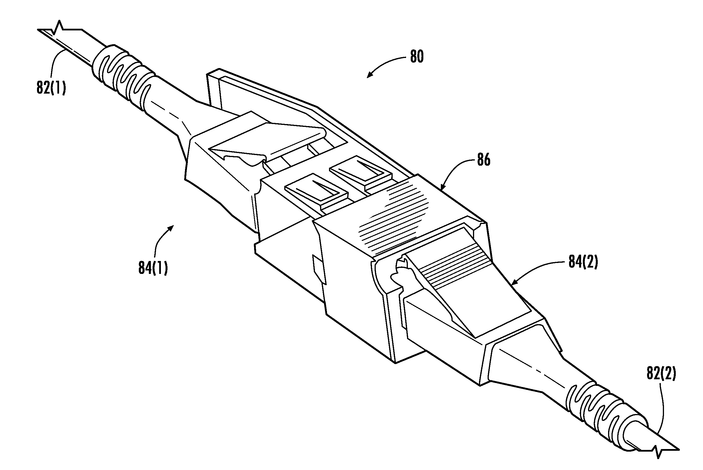
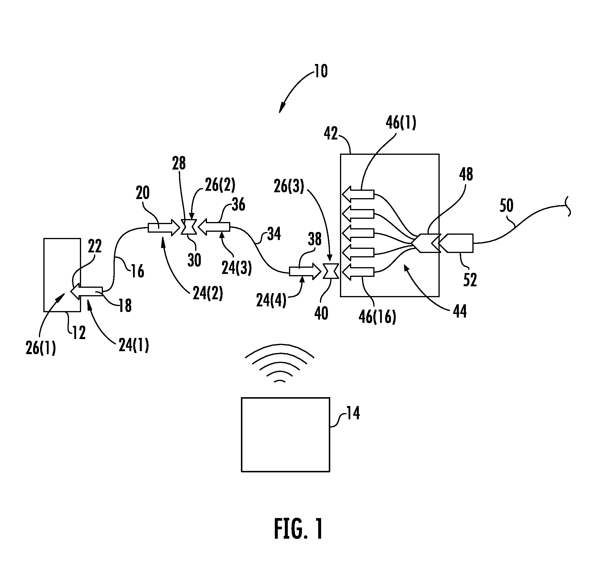
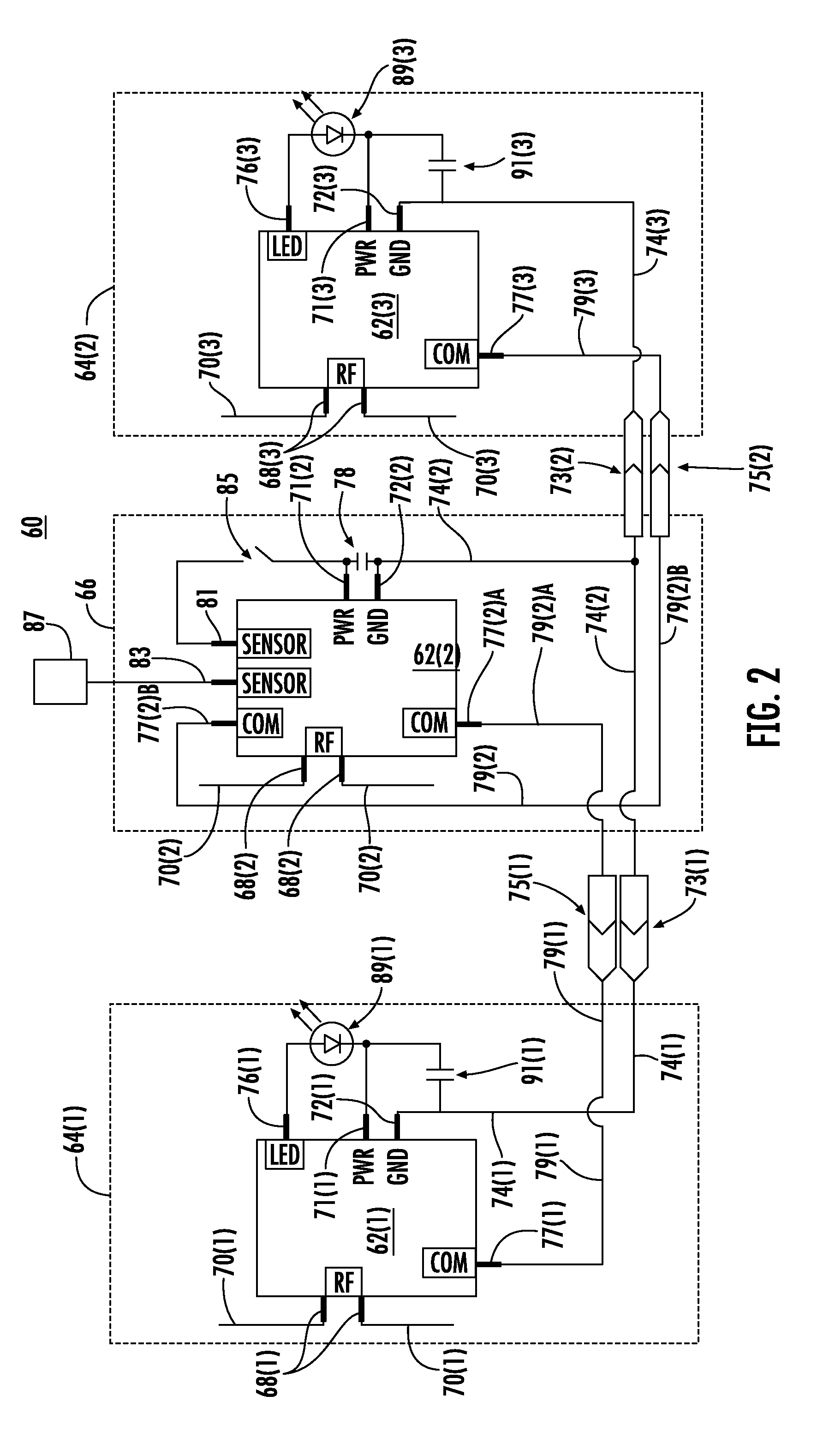
[0012]Embodiments disclosed in the detailed description include communication components that are radio frequency identification (RFID)-equipped to wirelessly communicate information regarding the communication component. This information may include an identification of the communication component. In certain embodiments disclosed herein, the communication components are fiber optic components. A transponder or other RFID circuit (also referred to as “RFID tag”) is provided in the fiber optic component for communicating wirelessly to an RFID reader or other transceiver. In this manner, the fiber optic component can be interrogated by an RFID reader that receives information concerning the fiber optic component to assist in mapping or other tracking of the fiber optic component and its connection to another fiber optic component. Detection of the physical connection of components can be accomplished via the electrical connection of circuits located on each component. In order that t...


PUM


Abstract

Radio frequency identification (RFID)-equipped communication components are disclosed. The communication components can include fiber optic components, such as fiber optic connectors and fiber optic adapters as examples. An RFID-equipped circuit is provided in the communication components to communicate information. In order that the electrical circuit be provided in the communication component without altering the communication component connection type, the circuit may be disposed in at least one recessed area of the communication component housing. In this manner, the communication component maintains its connection type such that it is compatible with a complementary communication component connection type for backwards compatibility while also being RFID-equipped. The circuit may also be provided in a substrate containing one or more electrical contacts coupled to the circuit such that a wired coupling is established with one or more electrical contacts provided in another communication component when connected.

Description

RELATED APPLICATIONS[0001]This application is related to U.S. patent application Ser. No. 11 / 590,505 entitled “Radio Frequency Identification of Component Connections,” and U.S. patent application Ser. No. 11 / 590,513 entitled “System for Mapping Connections Using RFID Function,” both of which are hereby incorporated herein by reference in their entireties.BACKGROUND[0002]1. Field[0003]The technology of the present application is related to use of radio frequency (RF) communications in communication connections, such as fiber optic components and fiber optic component connections, as examples.[0004]2. Technical Background[0005]Benefits of optical fiber use include extremely wide bandwidth and low noise operation. Because of these advantages, optical fiber is increasingly being used for a variety of applications, including but not limited to broadband voice, video, and data transmission. Fiber optic networks employing optical fibers are being developed and used to deliver voice, video...

Claims


Application Information

Patent Timeline
Patent Type & Authority Applications(United States)
IPC IPC(8): H04B10/12H04Q5/22G02B6/36
CPCG02B6/3825G02B6/3895G02B6/3885G02B6/3879G02B6/3893
Inventor JONES, ASHLEY WESLEYTRAVIS, PETER TIMOTHYSUTHERLAND, JAMES SCOTT
Owner FIBER MOUNTAIN INC
Why Eureka
Try Eureka