Fuel cell system and method for controlling same

a fuel cell and system technology, applied in the field of fuel cell systems, can solve problems such as deterioration of members, and achieve the effect of suppressing the deterioration of the fuel cell system and suppressing the increase of the number of implementations

Active Publication Date: 2011-11-10
NISSAN MOTOR CO LTD
View PDF5 Cites 25 Cited by
  • Summary
  • Abstract
  • Description
  • Claims
  • Application Information

AI Technical Summary

Benefits of technology

[0012]According to the present invention, periodically changing a pressure of a fuel gas at a fuel electrode based on the first pressure change pattern which implements pressure change at the first pressure width can agitate the fuel electrode side gas. With this, the fuel electrode side gas can be made even.
[0013]Moreover, according to the present invention, the fuel gas supply quantity in the implementation period of one control pattern is increased, thus it is possible to suppress increase in the number of implementations of the pressure rise-fall per unit period. With this, a stress applied to the fuel cell or fuel gas supply components can be relieved, thus it is possible to suppress deterioration of the fuel cell system.

Problems solved by technology

The thus caused gas unevenness is a cause for deteriorating members included in the fuel cell.

Method used


Image

  • Fuel cell system and method for controlling same
  • Fuel cell system and method for controlling same
  • Fuel cell system and method for controlling same

Examples


first embodiment

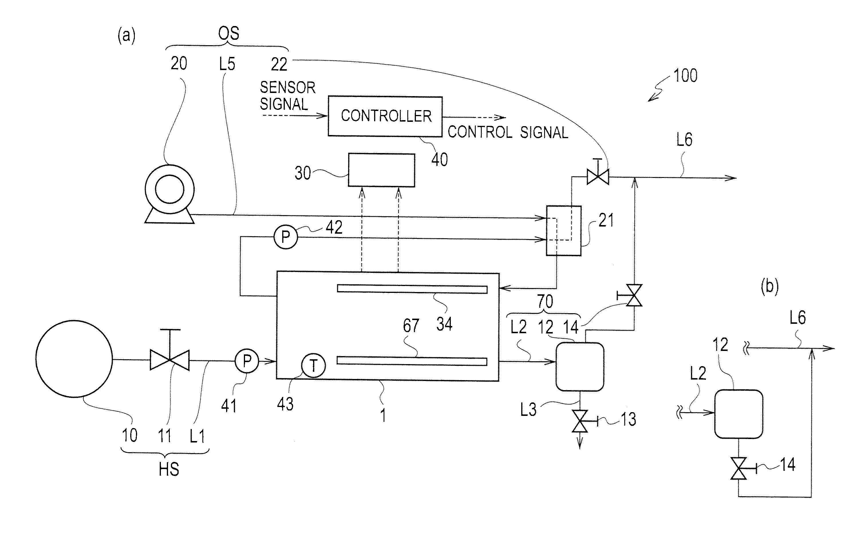
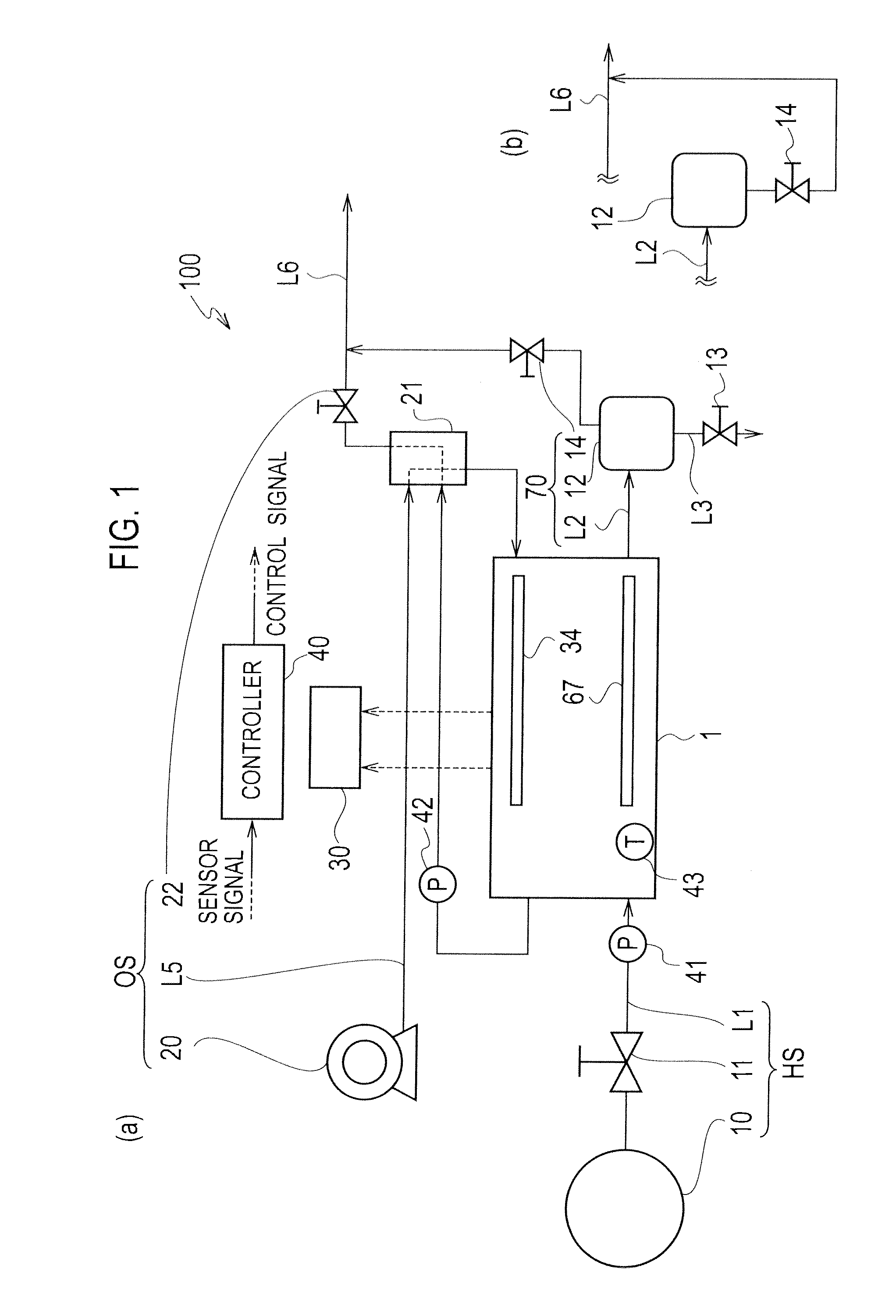
[0036]FIG. 1(a) is a block diagram schematically showing a structure of a fuel cell system 100 according to the first embodiment of the present invention. The fuel cell system 100 is installed, for example, in a vehicle that is a mobile object, where the vehicle is driven by an electric power supplied from the fuel cell system 100.

[0037]The fuel cell system 100 is principally provided with a fuel cell stack 1 including a plurality of stacked fuel cells. Each of the fuel cells included in the fuel cell stack 1 is so formed that a fuel cell structure is sandwiched between a pair of separators, where the fuel cell structure has such a structure that a fuel electrode 67 (refer to after-described FIG. 4) and an oxidant electrode 34 (refer to after-described FIG. 4) sandwich therebetween a solid polymer electrolyte membrane.

[0038]In the fuel cell stack 1, corresponding to each of the fuel gas and the oxidant gas, a pair of internal flow channels are so formed as to extend in a stack direc...

second embodiment

[0080]Hereinafter, the fuel cell system 100 according to the second embodiment of the present invention is to be set forth. The fuel cell system 100 according to the second embodiment is different from the fuel cell system 100 according to the first embodiment in terms that the hydrogen quantity which is supplied to the fuel electrode 67 of the fuel cell stack 1 attributable to the pressure change by the pressure change pattern is variably set according to the operation condition of the fuel cell system 100. In addition, the structure of the fuel cell system 100 according to the second embodiment is the same as that according to the first embodiment, therefore repeated explanations are to he omitted and differences are to be mainly set forth below.

[0081]FIG. 10 is a flowchart showing a control method of the fuel cell system 100 according to the second embodiment of the present invention, specifically, showing process procedures of a method of supplying hydrogen to the fuel electrode...

third embodiment

[0095]Hereinafter, the fuel cell system 100 according to the third embodiment of the present invention is to be set forth. Herein, the structure of the fuel cell system 100 according to the third embodiment is like those according to the first and second embodiments, therefore repeated explanations are to be omitted and differences are to be mainly set forth.

[0096]The controller 40 controls the fuel cell system 100 in the following manner. The controller 40 supplies air and hydrogen to the fuel cell stack 1, to thereby implement the generation by the fuel cell stack 1. In this case, the controller 40 supplies air and hydrogen such that the pressure of each of air and hydrogen which are supplied to the fuel cell stack 1 becomes a predetermined operation pressure. This operation pressure is set, for example, as a certain standard value irrespective of the power generated by the fuel cell stack 1, or set as variable values according to the power generated by the fuel cell stack 1.

[0097...


PUM

PropertyMeasurementUnit
poweraaaaaaaaaa
pressureaaaaaaaaaa
pressure widthaaaaaaaaaa

Abstract

A fuel cell system 100 includes: a fuel cell 1 for generating a power by causing an electrochemical reaction between an oxidant gas supplied to an oxidant electrode 34 and a fuel gas supplied to a fuel electrode 67; a fuel gas supplier HS for supplying the fuel gas to the fuel electrode 67; and a controller 40 for controlling the fuel gas supplier HS to thereby supply the fuel gas to the fuel electrode 67, the controller 40 being configured to implement a pressure change when an outlet of the fuel electrode 67 side is closed, wherein based on a first pressure change pattern for implementing the pressure change at a first pressure width API, the controller 40 periodically changes a pressure of the fuel gas at the fuel electrode 67.

Description

TECHNICAL FIELD[0001]The present invention relates to a fuel cell system.BACKGROUND ART[0002]Conventionally, such a fuel cell system is known as is provided with a fuel cell where a fuel gas (for example, hydrogen) is supplied to a fuel electrode and an oxidant gas (for example, air) is supplied to an oxidant electrode to thereby make an electrochemical reaction of these gases, thus implementing a power generation.[0003]With respect to the fuel cell system of the above type, nitrogen included in the air is permeated to the fuel electrode side, so that the fuel electrode has a portion having a high nitrogen concentration, that is, a portion having a low hydrogen concentration. The thus caused gas unevenness is a cause for deteriorating members included in the fuel cell. Then, Patent Literature 1 discloses a method of changing gas pressures of the fuel electrode and oxidant electrode to thereby purge the water of the fuel cell and the accumulated unreactive gas.CITATION LISTPatent Lit...

Claims


Application Information

Patent Timeline
Patent Type & Authority Applications(United States)
IPC IPC(8): H01M8/04
CPCH01M8/04179H01M8/04365H01M8/04388Y02E60/50H01M8/04753H01M2008/1095H01M8/04395H01M8/04104
Inventor ICHIKAWA, YASUSHIIKEZOE, KEIGOGOTO, KENICHINAKAYAMA, KENKUMADA, MITSUNORITOMITA, YOUSUKE
Owner NISSAN MOTOR CO LTD
Why Eureka
Try Eureka