Method of regulating CSF drainage

a technology of csf drainage and drainage channel, which is applied in the direction of volume/mass flow by thermal effects, wound drainage, intravenous devices, etc., can solve the problems of large risk of passage becoming obstructed, flowmeters are not used, pressure difference sensors generally present problems of stability and drift over time, etc., to achieve effective and reliable drainage

Active Publication Date: 2011-11-10
SOPHYSA SA
View PDF6 Cites 12 Cited by
  • Summary
  • Abstract
  • Description
  • Claims
  • Application Information

AI Technical Summary

Benefits of technology

[0008]As described in greater detail in the description below, the implantable drainage device according to exemplary embodiments of the invention advantageously enables cerebr...

Problems solved by technology

The pressure difference must then be measured between the inlet and the outlet of a very narrow passage of small diameter, thereby specifically running a major risk of the passage becoming obstructed.
Furthermore, a press...

Method used


Image

  • Method of regulating CSF drainage
  • Method of regulating CSF drainage
  • Method of regulating CSF drainage

Examples


Embodiment Construction

Mass Flowmeter

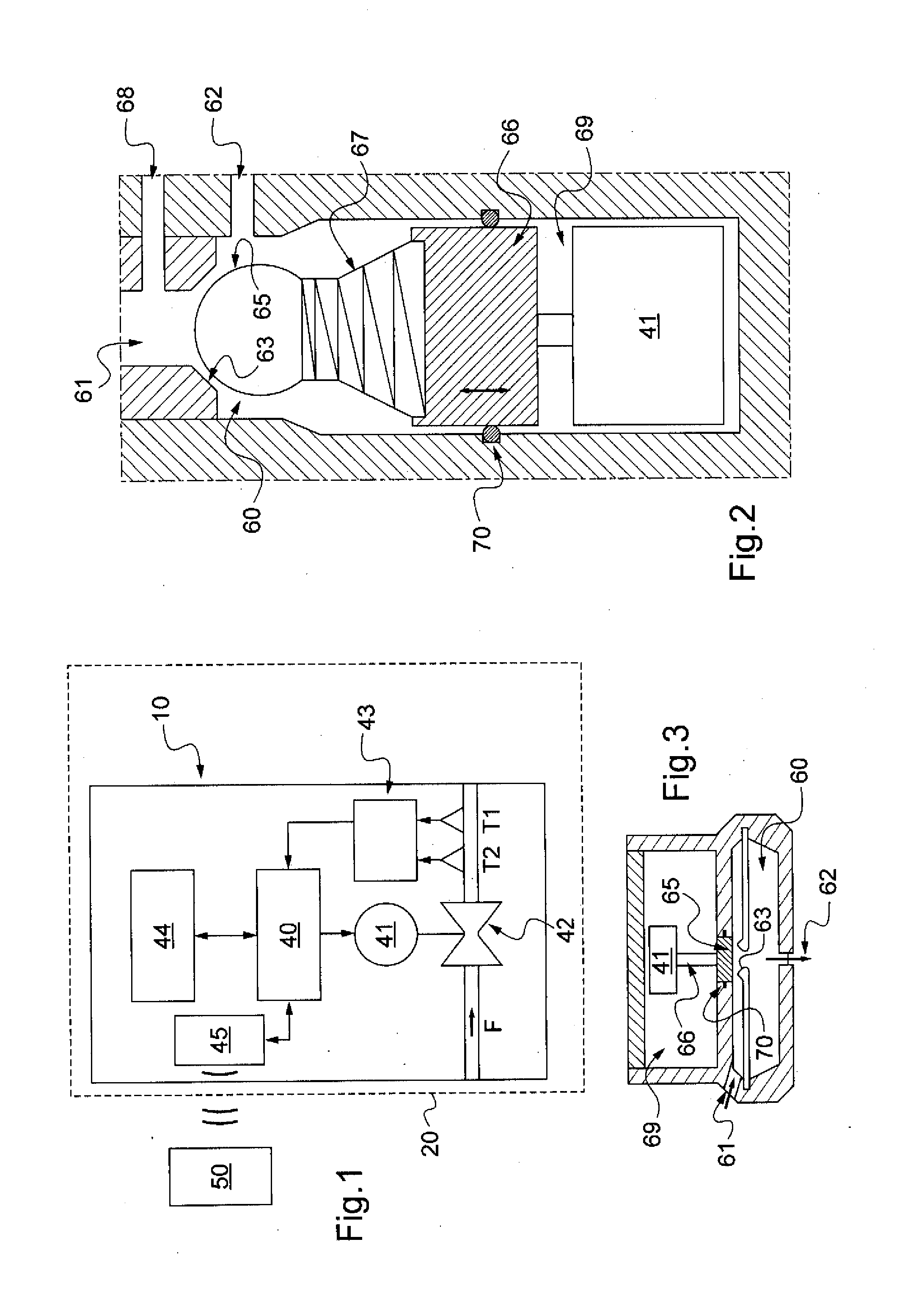
[0009]The term “mass flowmeter” is used to designate a Coriolis effect flowmeter or a thermal flowmeter, i.e. a meter providing measurements of the flow rate of a fluid that depends on the thermal capacity of the fluid. A mass flowmeter therefore needs to be rated as a function of the nature of the fluid for which it is desired to measure the flow rate. Conventionally, the operating principle of a mass flowmeter relies on evaluating heat exchange between the fluid and its environment while the fluid flows between an upstream point and a downstream point. By way of example, the evaluation may result from measuring the power required for maintaining a constant temperature difference between those two points, or conversely from measuring the temperature at the downstream point while the temperature at the upstream point is kept constant. In order to evaluate the flow rate, the mass flowmeter therefore has no need to make use of the pressure difference Pd from upstream to ...


PUM


Abstract

An implantable drainage device for draining the cerebro-spinal fluid of a patient, the device including:
    • a drainage valve including a valve member and a valve seat;
    • a control unit suitable for modifying an operating parameter of said valve, at least as a function of a measurement (D) of the fluid flow rate through said valve;
    • an actuator controlled by the control unit, suitable for modifying the operation of said valve as a function of said operating parameter as modified by the control unit; and
    • a mass flowmeter suitable for evaluating said flow rate of fluid through said valve.

Description

[0001]The invention relates to an implantable drainage device for draining the cerebro-spinal fluid (CSF) of a patient, and it also relates to methods of implementing the device. Such a device is intended in particular for treating hydrocephalus. It serves to shunt the cerebro-spinal fluid contained in the ventricles in the cranial cavity to some other site for resorption, e.g. the peritoneal cavity.BACKGROUND OF THE INVENTION[0002]Conventionally, a drainage device comprises a drainage valve presenting operation that is modifiable as a function of a measured pressure difference, as described in DE 196 54 990. The pressure difference must then be measured between the inlet and the outlet of a very narrow passage of small diameter, thereby specifically running a major risk of the passage becoming obstructed. Furthermore, a pressure difference sensor generally presents problems of stability and of drift over time.[0003]Also, international application WO 2006 / 115724 discloses an implant...

Claims


Application Information

Patent Timeline
IPC IPC(8): A61M1/00
CPCA61M27/006G01F1/68A61M2205/3379
Inventor NEGRE, PHILIPPEBOYER, CHRISTOPHEMOUREAUX, CHRISTOPHEBONNAL, OLIVIER
Owner SOPHYSA SA
Why Eureka
Try Eureka