Balloon catheter system and methods of use thereof

a balloon catheter and balloon surface technology, applied in the field of medical balloon catheters, can solve the problems of increasing the length of the balloon surface in contact with the blood vessel walls, preventing designers from developing new rapid exchange catheter implementations, etc., and preventing substantial pressure changes. , to achieve the effect of enhancing the retention of debris and preventing substantial pressure changes

Inactive Publication Date: 2011-11-10
ANGIOSLIDE
View PDF1 Cites 31 Cited by
  • Summary
  • Abstract
  • Description
  • Claims
  • Application Information

AI Technical Summary

Benefits of technology

[0040]Furthermore, in accordance with an embodiment of the method, the step of pulling includes pulling the inner conduit of the balloon catheter in a proximal direction to form the cavity, such that all of the surface portions of the middle portion are internally disposed within the cavity to enhance retention of the debris.
[0041]Furthermore, in accordance with an embodiment of the method, the catheter includes a mechanism for preventing substantial pressure changes

Problems solved by technology

This arrangement, wherein the guidewire tube is affixed to the catheter's shaft at the location of its lateral port, usually prevents designers from developing new rapid exchange catheter implementations which requires manipulating its inner sh

Method used


Image

  • Balloon catheter system and methods of use thereof
  • Balloon catheter system and methods of use thereof
  • Balloon catheter system and methods of use thereof

Examples


Embodiment Construction

Notation Used Throughout

[0064]The following notation is used throughout this document.

TermDefinitionDCADirectional coronary atherectomyELCAExcimer Laser Coronary AngioplastymmmillimeterPAPolyamidePEPolyethylenePETPolyethylene terephtalatePLOSAPhysiologic low stress angioplasty

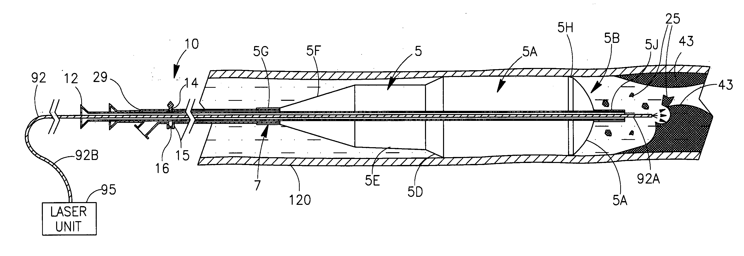
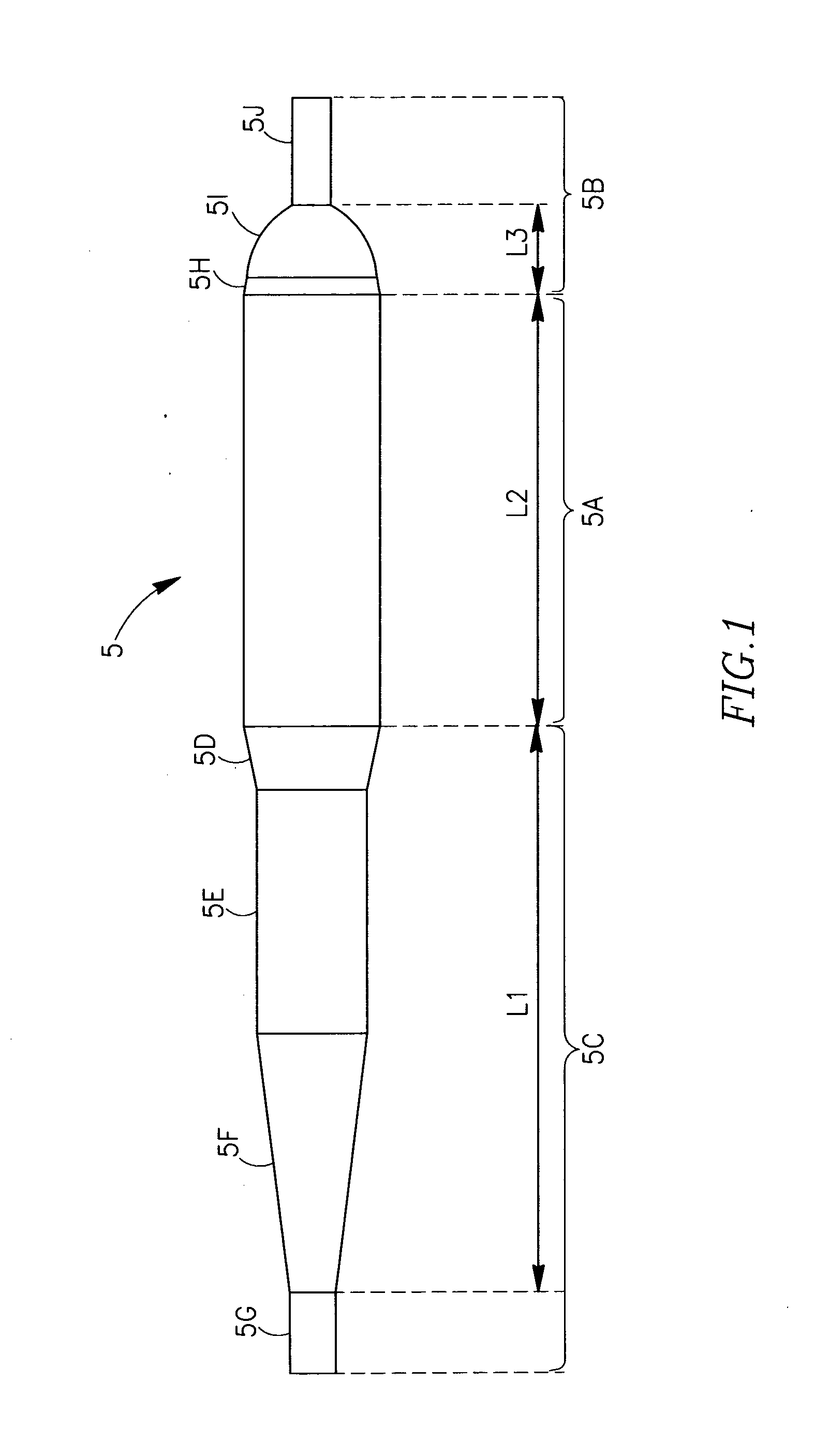
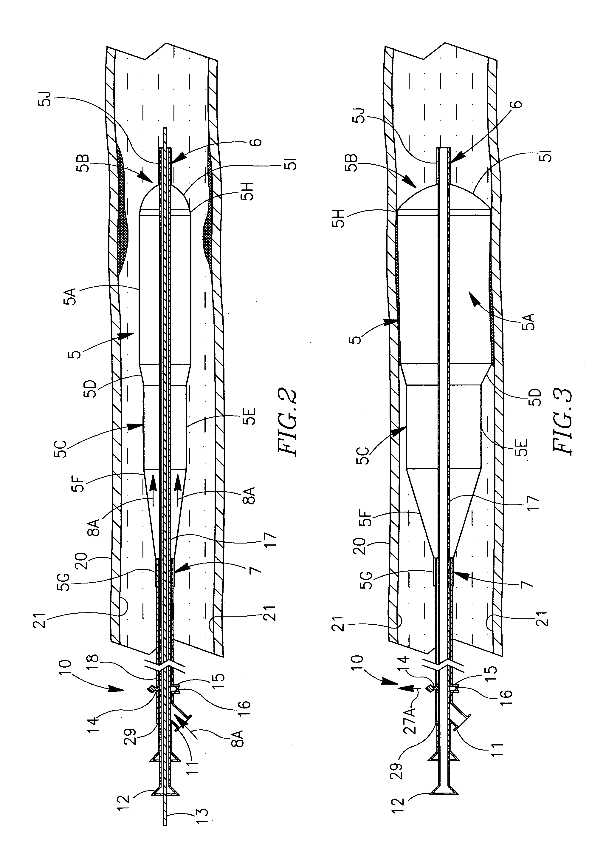
[0065]It is noted that in the following description and in the claims of the present application, the terms “distal” and “proximal” are defined as follows: the catheter side or end which is inserted into the body first is referred to as the distal side or distal end and the trailing side or end of the catheters part of which remains outside the body after insertion of the catheter is referred to as the proximal side. For example, in the balloon catheter 10 of FIG. 2, the graduated scale 19 is disposed on the proximal side of the catheter 10 and the cylindrical portion 5J is disposed near the distal side or distal end of the catheter 10.

[0066]Similarly, when referring to sides, parts or portions of the stepped b...


PUM


Abstract

A catheter including an outer conduit and an inner conduit movably disposed therein. The distal tip of the inner conduit extends beyond the distal tip of the outer conduit. An inflatable balloon has a first margin attached to the distal tip of the outer conduit, and a second margin attached to the portion of the inner conduit extending beyond the distal tip of the outer conduit. The balloon includes a middle portion, an inflatable distal side portion having at least one tapering part and an inflatable proximal side portion having at least one tapering portion. The length of proximal side portion is equal to or larger than the length of the middle portion. The distal end portion of the balloon is capable of intussuscepting upon proximal movement of the inner conduit within the outer conduit. The catheter includes an inflation/deflation port for introducing and removal of inflating fluid.

Description

CROSS-REFERENCE TO RELATED US APPLICATIONS[0001]This application claims priority from and the benefit of U.S. Provisional Patent Application Ser. No. 61 / 077,496 filed on Jul. 2, 2008 entitled “CORRUGATED BALLOON CATHETER SYSTEM AND METHODS OF USE THEREOF”, U.S. Provisional Patent Application Ser. No. 61 / 077,520 filed on Jul. 2, 2008 entitled “CORRUGATED BALLOON CATHETER AND METHODS OF USE THEREOF” and U.S. Provisional Patent Application Ser. No. 61 / 143,847 filed on Jan. 12, 2009 entitled “BALLOON AND CATHETER SYSTEM AND METHODS FOR MAKING SAME” all of which are incorporated herein by reference in their entirety.FIELD OF THE INVENTION[0002]This invention relates in general to the fields of medical balloon catheters and more particularly to catheters and systems having intususceptible inflatable elements, systems including such catheters and methods of use and manufacturing of such catheters and systems.BACKGROUND OF THE INVENTION[0003]Catheters are used in various interventional proc...

Claims


Application Information

Patent Timeline
IPC IPC(8): A61M29/00A61B17/22A61F2/958
CPCA61B17/22032A61B17/320725A61B18/245A61B2017/2215A61B2017/22074A61B2017/22079A61B2017/22067
Inventor BESSER, DORONHARARI, ERAN
Owner ANGIOSLIDE
Why Eureka
Try Eureka