Receiving part for receiving a rod for coupling the rod to a bone anchoring element, bone anchoring device, method and tool for assembling the same

Inactive Publication Date: 2011-11-10
BIEDERMANN TECH GMBH & CO KG
View PDF42 Cites 86 Cited by
  • Summary
  • Abstract
  • Description
  • Claims
  • Application Information

AI Technical Summary

Benefits of technology

[0015]The tool is easy to hand

Problems solved by technology

If a head of an anchoring element is freely pivotable with respect to a receiving part, alignment of the receiving part and insertion o

Method used


Image

  • Receiving part for receiving a rod for coupling the rod to a bone anchoring element, bone anchoring device, method and tool for assembling the same
  • Receiving part for receiving a rod for coupling the rod to a bone anchoring element, bone anchoring device, method and tool for assembling the same
  • Receiving part for receiving a rod for coupling the rod to a bone anchoring element, bone anchoring device, method and tool for assembling the same

Examples


Embodiment Construction

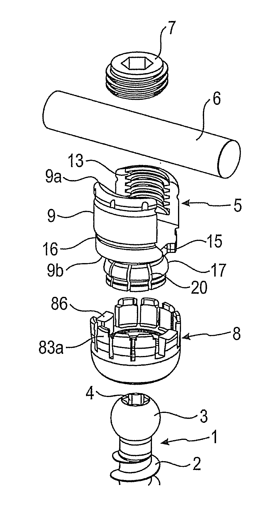
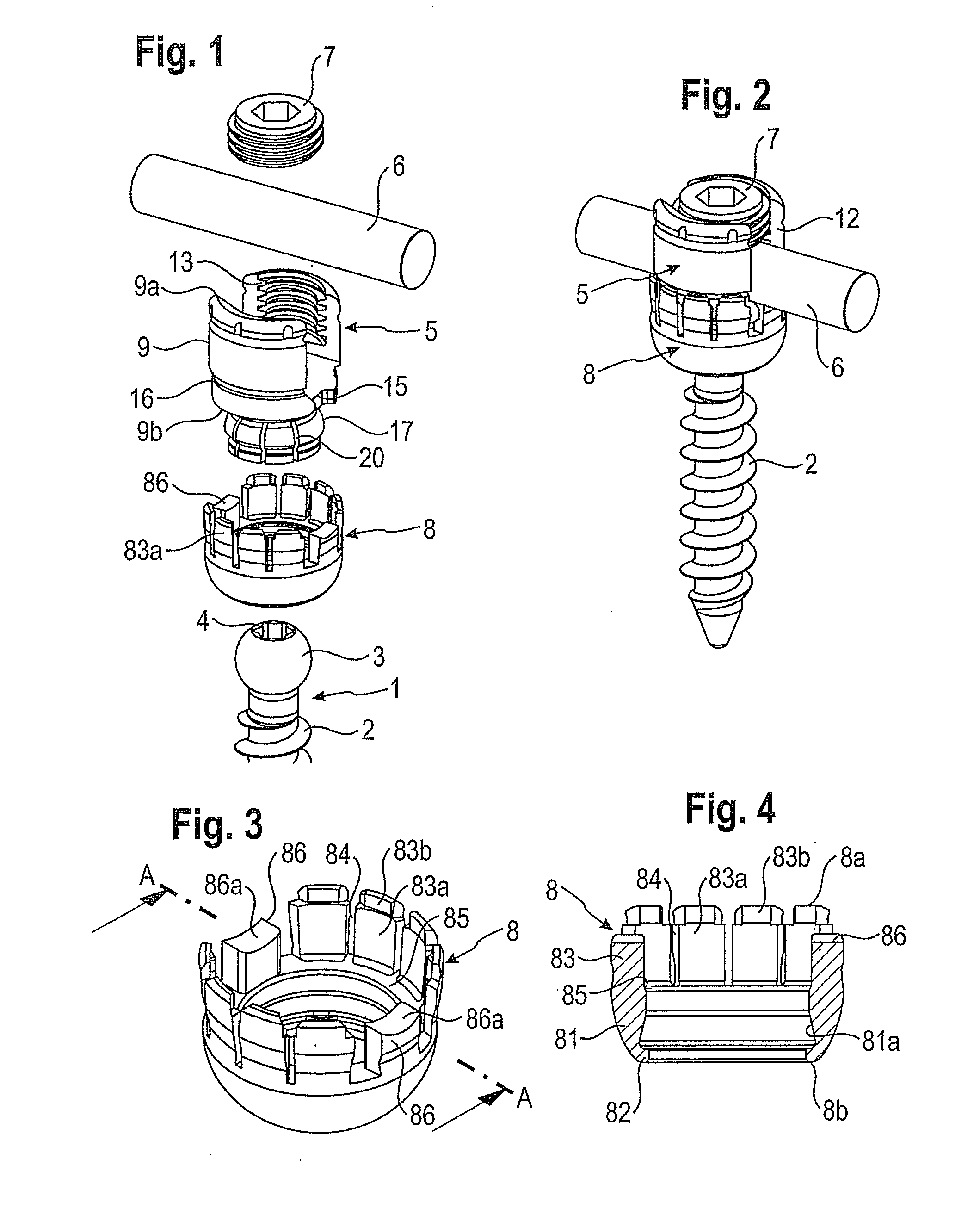
[0046]As shown in FIGS. 1 to 7, a bone anchoring device according to an embodiment of the invention includes a bone anchoring element 1 in the form of a bone screw having a threaded shaft 2 and a head 3 with a curved surface portion. In this embodiment the head is spherical segment-shaped. The head 3 has a recess 4 for engagement with a tool. The bone anchoring device also includes a receiving part body 5 for receiving a rod 6 to connect it to the bone anchoring element 1. Further, a fixation element 7 in the form of an inner screw is provided for fixing the rod 6 in the receiving part body 5. The bone anchoring device also includes a locking ring 8 for locking the head 3 in the receiving part body 5.

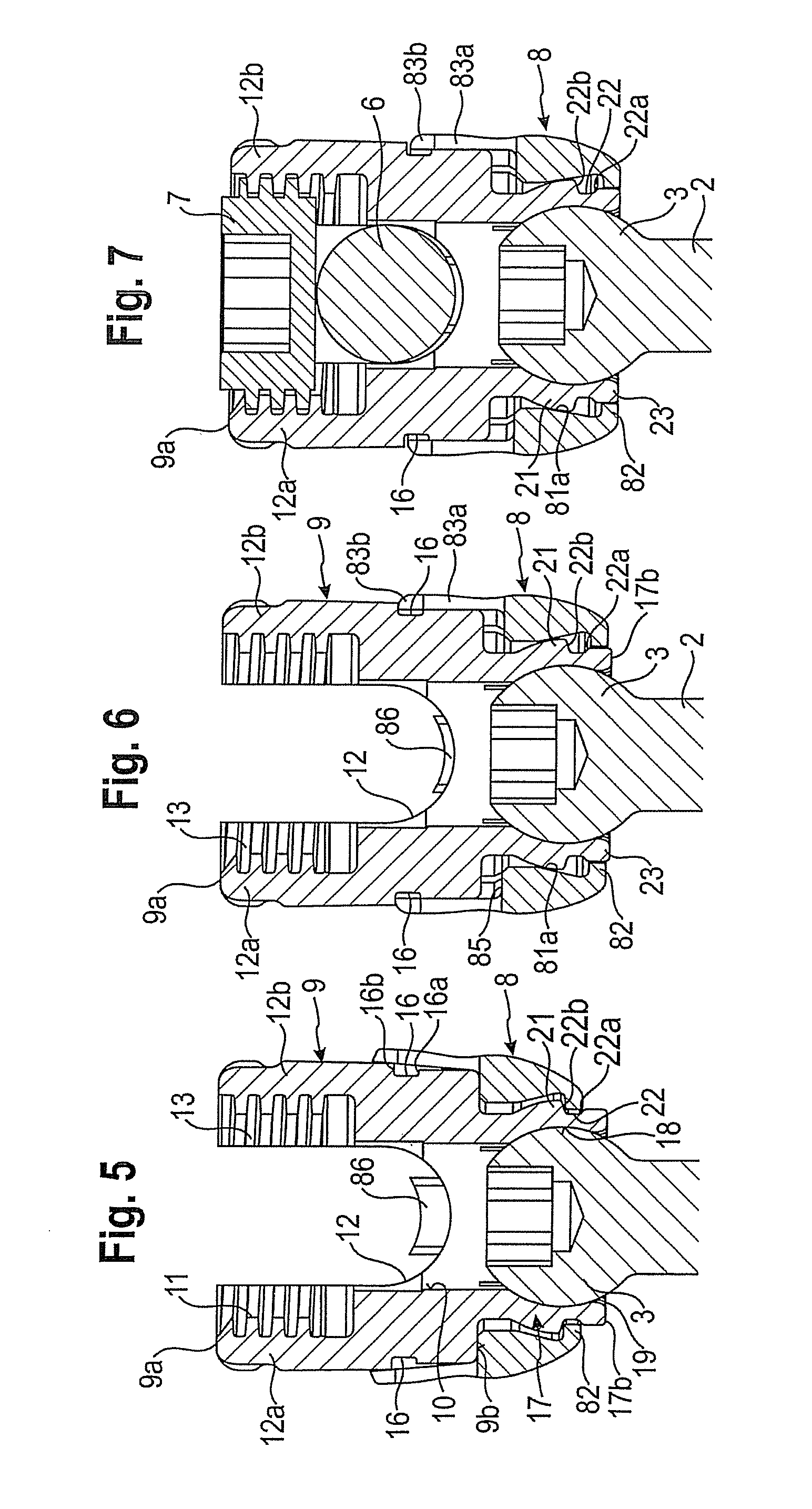
[0047]The receiving part body 5 includes a rod receiving portion 9, which is substantially cylindrical and which has a first end 9a and a second end 9b opposite the first end 9a. A coaxial first bore 10 is provided at the second end 9b as shown in FIGS. 5 to 7. The diameter of the first...


PUM

PropertyMeasurementUnit
Lengthaaaaaaaaaa
Forceaaaaaaaaaa
Flexibilityaaaaaaaaaa

Abstract

A receiving part for receiving a rod for coupling the rod to a bone anchoring element includes a receiving part body with a first end and a second end; a rod receiving portion with a channel for receiving a rod, and a head receiving portion for accommodating a head of a bone anchoring element, the head receiving portion having an open end at the second end of the receiving part body and being flexible so as to allow introduction and clamping of the head; and a locking ring configured to be positioned around the head receiving portion, wherein the locking ring can assume a first position with respect to the receiving part body in which the locking ring is latched to the receiving part body in a position where the head receiving portion is expandable to facilitate insertion of a head of a bone anchoring element, and wherein the locking ring can assume a second position with respect to the receiving part body in which the locking ring is latched to the receiving part body in a position where the locking ring compresses the head receiving portion, such that when a bone anchoring element has a head inserted in the head receiving portion, the bone anchoring element is held adjustably at a first angular position relative to the receiving part. A method for assembling a bone anchoring device includes inserting the head of the bone anchoring element into the receiving part body; and moving the locking ring and the receiving part body relative to each other until the locking ring assumes the second position with respect to the receiving part body.

Description

CROSS-REFERENCE TO RELATED APPLICATION(S)[0001]The present application claims priority to and the benefit of U.S. Provisional Patent Application Ser. No. 61 / 331,518, filed May 5, 2010, the contents of which are hereby incorporated by reference in their entirety, and claims priority from European Patent Application EP 10 162 063.1, filed May 5, 2010, the contents of which are hereby incorporated by reference in their entirety.BACKGROUND[0002]1. Field of the Invention[0003]The invention relates to a receiving part for receiving a rod for coupling the rod to a bone anchoring element, a bone anchoring device with such a receiving part, a method and a tool for assembling the bone anchoring device. The receiving part includes a receiving part body and a locking ring. The locking ring can assume a first position in which it is latched with respect to the receiving part body and in which a head of the bone anchoring element can be inserted, and a second position in which it is latched with ...

Claims


Application Information

Patent Timeline
IPC IPC(8): A61B17/86B23P11/00A61B17/00
CPCA61B17/7032A61B17/7037A61B17/7074A61B17/8685A61B17/88A61B17/866Y10T29/5397Y10T29/53974Y10T29/49826Y10T29/53678Y10T29/49947Y10T29/53796Y10T29/53978A61B2017/00526Y10T29/49876
Inventor BIEDERMANN, LUTZDANNECKER, BERTHOLD
Owner BIEDERMANN TECH GMBH & CO KG
Why Eureka
Try Eureka