Transfer assist apparatus

a technology of assist devices and transfer devices, which is applied in the field of transfer assist devices, can solve the problems of not being able to trust the apparatus in the same degree, not being able to perform by oneself, and placing a large physical load on the nursing assistant and a large mental load on the care-receiver, so as to reduce the anxiety of the care-receiver

Inactive Publication Date: 2011-11-17
TOYOTA JIDOSHA KK
View PDF9 Cites 23 Cited by
  • Summary
  • Abstract
  • Description
  • Claims
  • Application Information

AI Technical Summary

Benefits of technology

[0008]The intention provides a transfer assist apparatus that performs

Problems solved by technology

For a care-receiver who cannot walk by oneself, it is not easy to perform by oneself the transfer movement of moving from a bed to a wheelchair.
Usually, a nursing assistant has to help, but the aid in transfer movement places a large physical load on the nursing assistant and a large mental load on the care-receiver.
It is obviously an important problem to ensure safety of the care-receiver during the transfer assist.
However, when the transfer assist apparatus is us

Method used


Image

  • Transfer assist apparatus
  • Transfer assist apparatus
  • Transfer assist apparatus

Examples


first embodiment

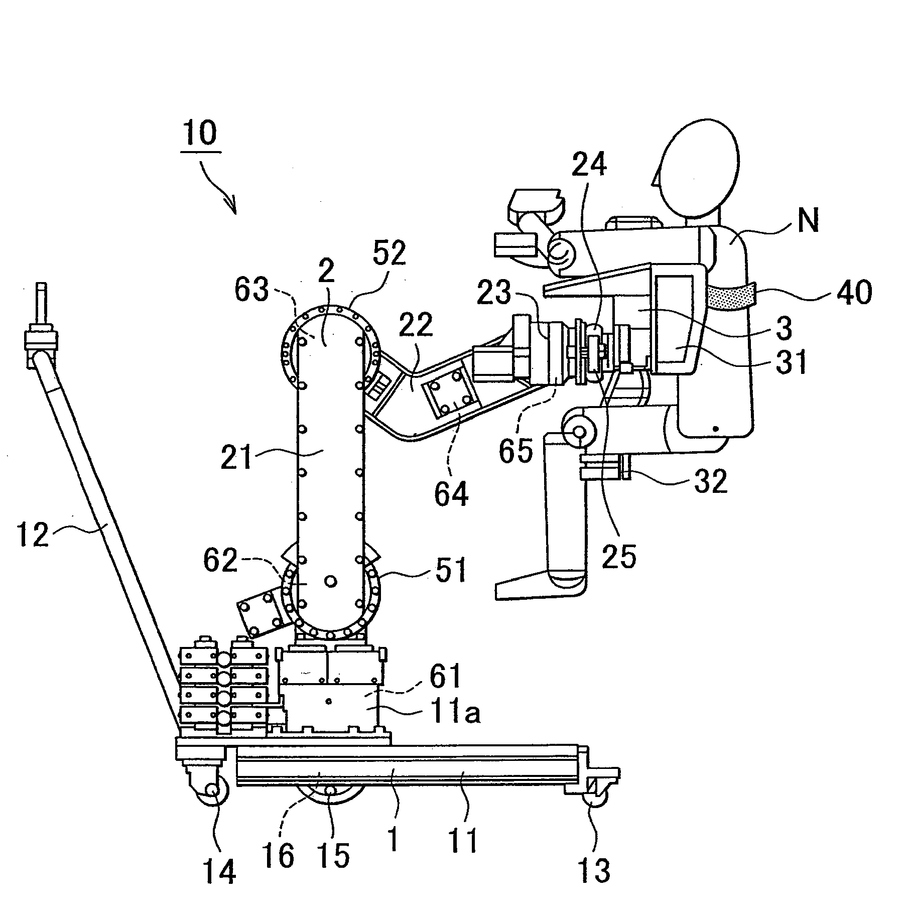
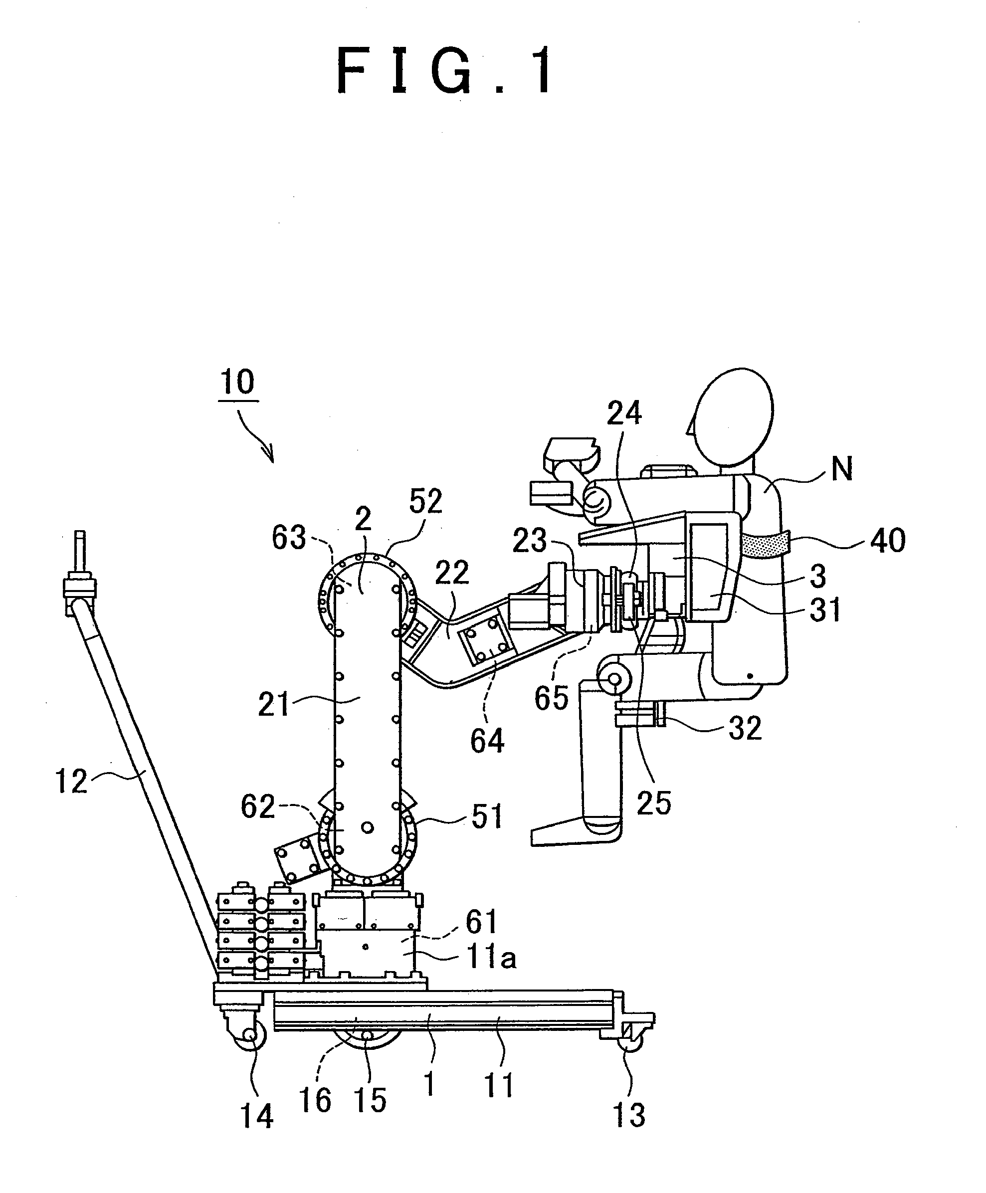
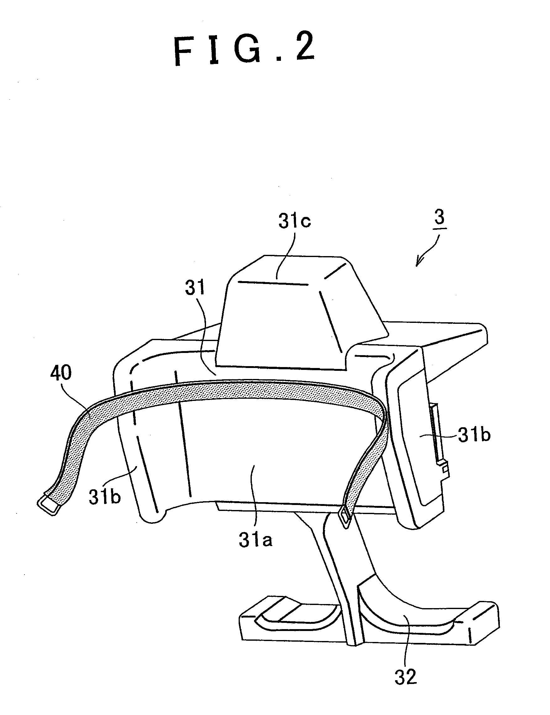
[0054](First Embodiment) the invention will be explained below. FIG. 1 is a side view of a transfer assist apparatus according to the first embodiment of the invention. A transfer assist apparatus 10 is provided with a carriage unit 1, a robot arm unit 2 coupled to the carriage unit 1, and a holding device 3 attached to the robot arm unit 2.

[0055]The carriage unit 1 has a carriage body 11, a handle section 12 for pushing and moving the carriage unit 1, a pair of left and right front aid wheels 13 attached to the front portion of the carriage body 11, a pair of left and right rear aid wheels 14 attached to the rear portion of the carriage body 11, and a pair of left and right drive wheels 15 that are attached to a substantially central portion of the carriage body 11 and drive the carriage unit 1. A pair of left and right sixth motors 16 that drive the drive wheels 15 is coupled to the pair of left and right drive wheels 15.

[0056]The robot arm unit 2 is a multijoint arm that has a fi...

second embodiment

[0099](Second Embodiment) the invention will be described below. The basic configuration of the second embodiment is similar to that of the first embodiment, but a specific feature of the second embodiment is that the motor speed is adjusted by adjusting a gain with the anxiety reduction control unit 110. FIG. 16 is a functional block diagram of the second embodiment. In the second embodiment, the speed limit unit 175 is not provided. Instead, the anxiety reduction control unit 110 is provided with a heart rate threshold recording unit 111 and a gain setting unit 112.

[0100]Here, several stages are set for a heart rate threshold, and a gain that determines a response speed of the motor is set correspondingly to these thresholds at several stages. For example, the gain is set to decrease with the increase in a sense of anxiety (heart rate) correspondingly to the anxiety threshold (heart rate threshold).

[0101]The gain setting unit 112 compares the heart rate of the care-receiver that i...

third embodiment

[0104](Third Embodiment) the invention will be described below. The basic configuration of the third embodiment is similar to that of the first embodiment, but a specific feature of the third embodiment is that optimum control is executed for each user. FIG. 17 is a functional block diagram of the third embodiment. In a case where one transfer assist apparatus 10 is shared by a plurality of care-receivers, reasons causing anxiety and degrees thereof differ among the care-receivers. In such a case, one control pattern should not be applied to all the care-receivers. Accordingly, in the third embodiment, the anxiety reduction control unit 100 is provided with a user database 200. Further, a data accumulation unit 300 is provided, and the sensor signals from the rotation sensors 71 to 75 and measurement values obtained with the anxiety measurement unit 50 are inputted in the data accumulation unit 300.

[0105]Anxiety thresholds (heart rate thresholds) and speed limit settings are recorde...


PUM


Abstract

A transfer assist apparatus includes an anxiety measurement unit that detects a physical change linked to a sense of anxiety in the care-receiver and measures a degree of anxiety in the care-receiver, and a control unit that control the drive unit correspondingly to a trajectory inputted by the operation unit and performs feedback control so as to reduce the degree of anxiety measured by the anxiety measurement unit. The anxiety measurement unit detects at least one of a heart rate, an amount of perspiration, a breathing rate, an eyeball movement, an electric resistance of skin, and a skin temperature as the physical change linked to a sense of anxiety in the care-receiver. The control unit sets a speed limit of the drive unit correspondingly to the degree of anxiety measured by the anxiety measurement unit and restricts the drive speed of the drive unit not to exceed the speed limit.

Description

BACKGROUND OF THE INVENTION[0001]1. Field of the Invention[0002]The invention relates to a transfer assist apparatus, for example, a transfer assist apparatus that assists in a transfer operation for a person who cannot walk by oneself to transfer from a bed to a wheelchair or from the wheelchair to the toilet seat.[0003]2. Description of the Related Art[0004]For a care-receiver who cannot walk by oneself, it is not easy to perform by oneself the transfer movement of moving from a bed to a wheelchair. Usually, a nursing assistant has to help, but the aid in transfer movement places a large physical load on the nursing assistant and a large mental load on the care-receiver. Apparatuses that assist the transfer movement of a care-receiver who cannot walk by oneself have recently been developed. For example, Japanese Patent Application Publication No. 2006-305092 (JP-A-2006-305092) discloses a transfer assist apparatus in which a tiltable strut is provided in a raised condition on a ro...

Claims


Application Information

Patent Timeline
IPC IPC(8): A61G7/10
CPCA61G7/1017A61G7/1048A61G7/1053A61G2203/46A61G7/1076A61G2200/52A61G7/1065
Inventor OKUMATSU, YOSHIHIRO
Owner TOYOTA JIDOSHA KK
Why Eureka
Try Eureka