Device for delivering a gas

a gas delivery and gas technology, applied in the direction of positive displacement liquid engines, pumping units, machines/engines, etc., can solve the problems of inability to correspondingly cool or discharge, and failure of membrane pumps, so as to achieve the effect of easy combination with various drive elements

Inactive Publication Date: 2011-11-17
ILLINOIS TOOL WORKS INC
View PDF3 Cites 20 Cited by
  • Summary
  • Abstract
  • Description
  • Claims
  • Application Information

AI Technical Summary

Benefits of technology

[0007]The simple yet nevertheless effective embodiment of the gear element, which acts as a rotation transducer, allows the piston to be driven in a simple yet nevertheless effective fashion such that it can move, to-and-fro, in an oscillatory fashion. This does not require a complicated design, but rather a few components that can easily be combined with various drive elements. By way of example, the drive can be an electric motor, but other drives are also feasible. All that is essential is that the drive element has a drive shaft to which the gear element can be attached in a rotationally fixed fashion.
[0008]In a preferred embodiment, the gasket is a sealing lip, which can rest against a pressure cylinder in a sealing fashion. However, other types of gasket are also feasible; all that is essential here is that the gasket has such a flexible and elastic design that it seals during an upward motion of the piston and can release the sealing effect during a downward motion of the piston such that air can stream past the piston.

Problems solved by technology

A disadvantage of this embodiment is that the air is heated as a result of the compression, but it cannot be correspondingly cooled or discharged.
This overheating may lead to a failure of the membrane pump.
Furthermore, it is also disadvantageous that the membrane-pump device and the sealing container substantially have an integral design and the former cannot easily be replaced.
By way of example, it is difficult to combine the membrane device with a new sealing container when the sealing container is empty; this, in particular, is not particularly environmentally friendly.

Method used


Image

  • Device for delivering a gas
  • Device for delivering a gas
  • Device for delivering a gas

Examples


Embodiment Construction

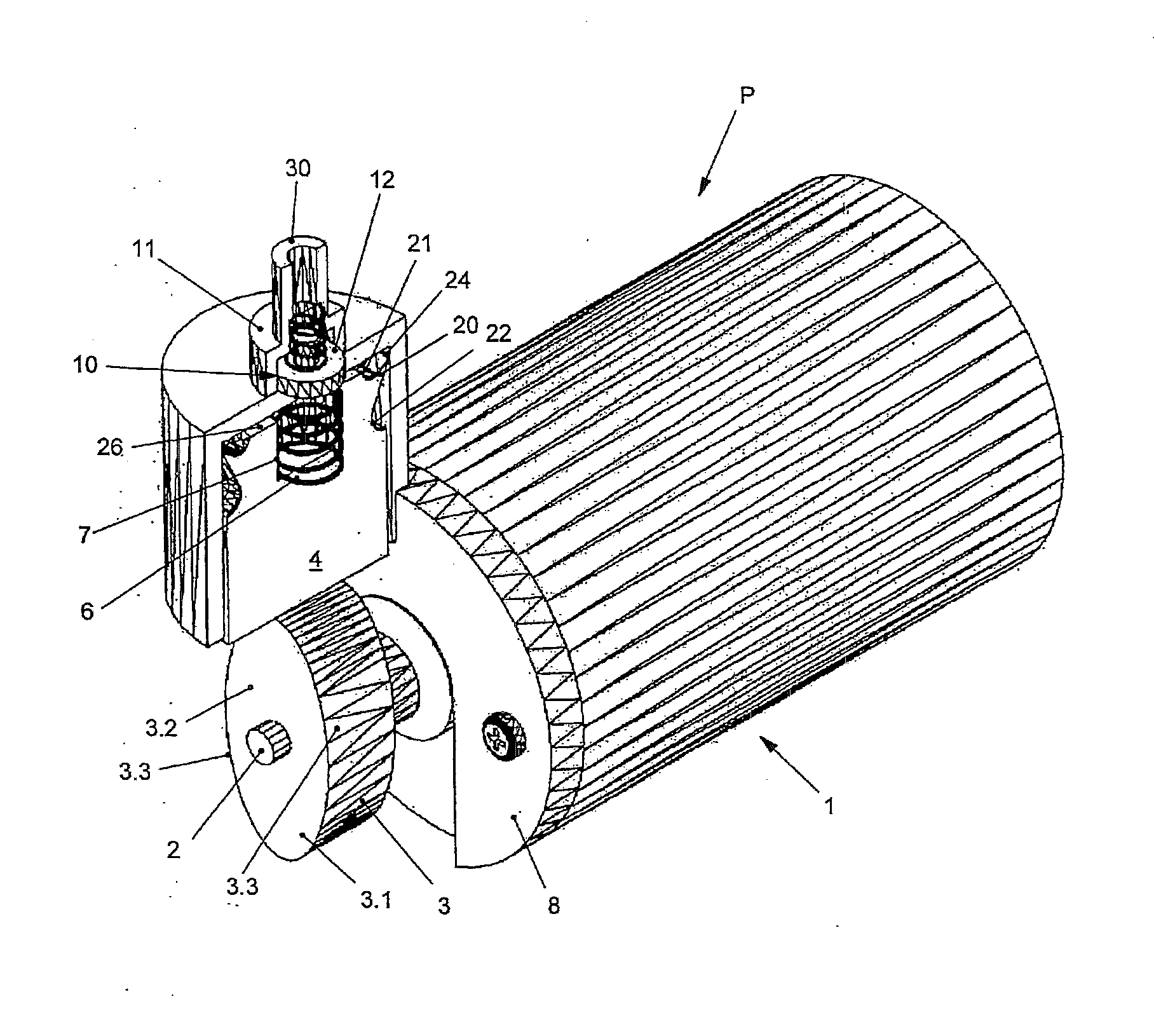
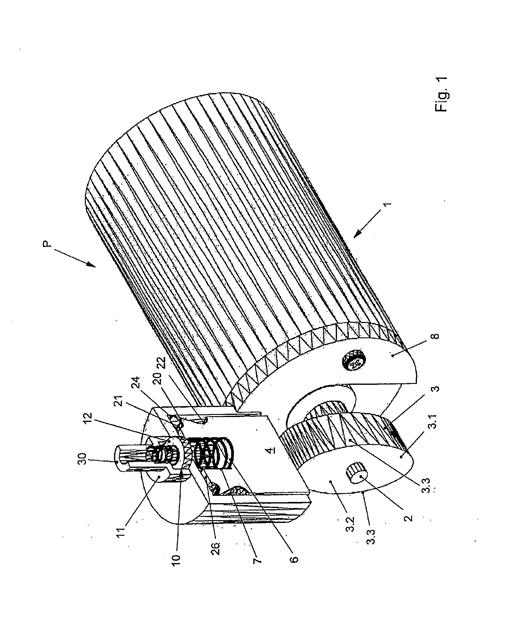
[0034]FIG. 1 shows that the device P for delivering a gas from a pressure chamber 5 has a drive 1 with a drive shaft 2, to which a gear element 3 has been attached in a rotationally fixed fashion. The drive 1 is an electric motor in the preferred embodiment.

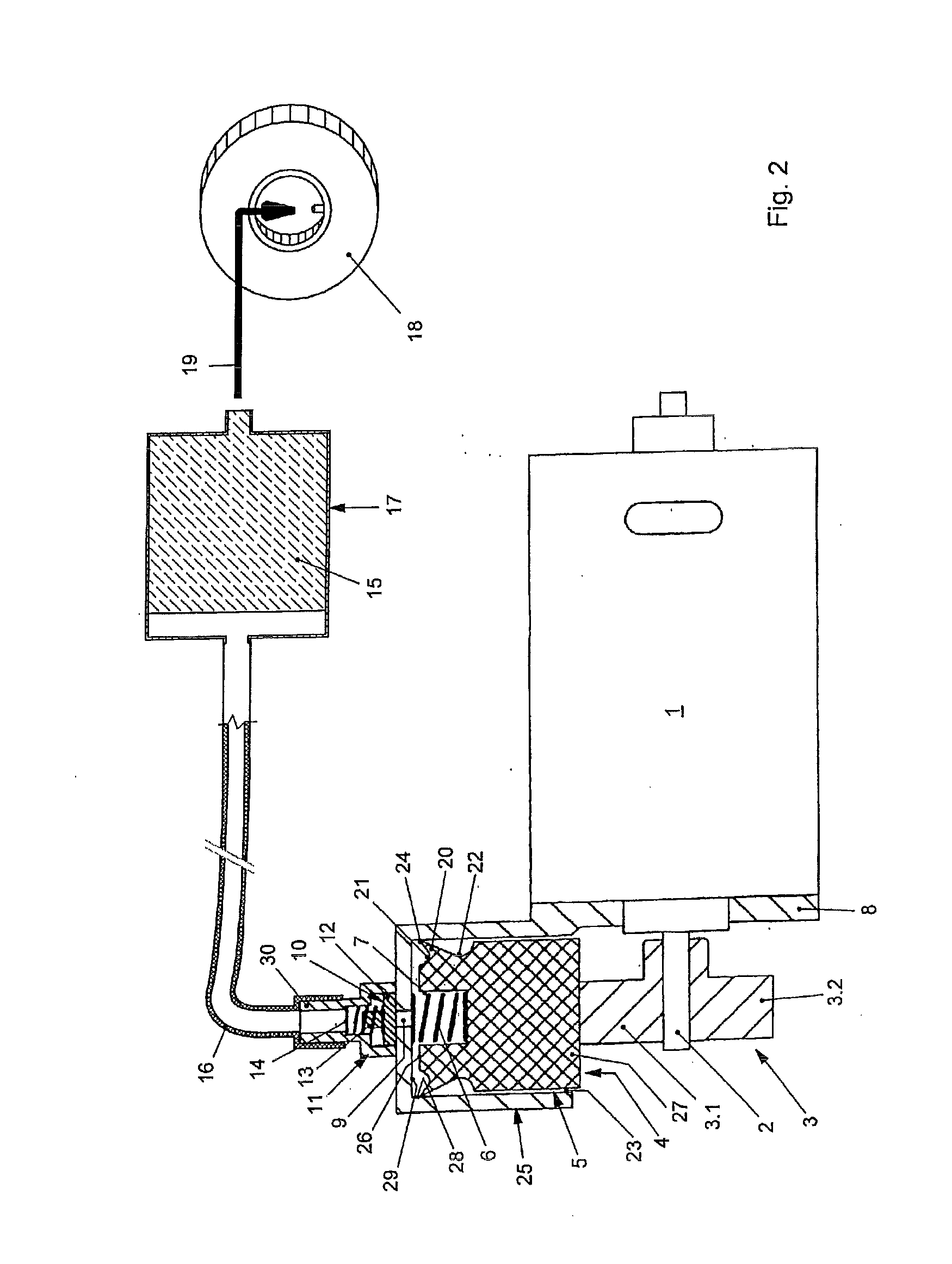
[0035]As shown in FIG. 1, the gear element 3 is a double cam 3 with a first projection 3.1 and a second projection 3.2. The double cam 3 has been attached to the drive shaft 2 such that the two projections 3.1 and 3.2 protrude from the drive shaft in a substantially mirror-symmetric fashion. The elliptic shape of the double cam 3 converts the rotational motion of the drive shaft 2 into an oscillatory motion. The oscillatory motion brings about upward and downward motion of a piston 4, which is mounted such that it can move to-and-fro in a pressure chamber 5 (see FIG. 2).

[0036]A force-storage element 6 holds the piston 4 against the gear element 3 under pretension such that the piston is in constant contact with the gear element 3...


PUM

PropertyMeasurementUnit
speedaaaaaaaaaa
distanceaaaaaaaaaa
pressureaaaaaaaaaa

Abstract

In a device (P) for delivering a gas out of a pressure chamber (5), in particular into a container (17) for dispensing a sealant (15) from said container into a tire (18) of a vehicle and/or for inflating the tire, wherein a plunger (4) is arranged to be oscillatingly movable in the pressure chamber, a gasket (20) is associated with the plunger and changes the distance thereof from a pressure chamber wall (28) when there is a change in the direction of movement of the plunger.

Description

BACKGROUND OF THE INVENTION[0001]The invention relates to a device for delivering a gas from a pressure chamber into a container, in particular, for dispensing a sealant from this container into a tire of a vehicle and / or for inflating the tire, wherein a piston is arranged in the pressure chamber such that it can move in an oscillatory fashion.[0002]DE 10 2004 042 911 A1 has disclosed a device for delivering a gas from a pressure chamber into a container, in particular, for dispensing a sealant from this container into a tire of a vehicle and for inflating the tire. A compressor can be connected to the sealant container disclosed in said document. This compressor may also be embodied as a membrane compressor, which compresses air that is present in the sealing container in order to press sealant out of the sealant container. A disadvantage of this embodiment is that the air is heated as a result of the compression, but it cannot be correspondingly cooled or discharged. This overhea...

Claims


Application Information

Patent Timeline
Patent Type & Authority Applications(United States)
IPC IPC(8): B65B31/00
CPCB29C73/166F04B27/0414F04B39/0016F04B39/0005F04B35/04
Inventor STEHLE, MICHAEL
Owner ILLINOIS TOOL WORKS INC
Why Eureka
Try Eureka