Switching scheme for step up-step down converters using fixed frequency current-mode control

a technology of fixed frequency current and switching regulator, which is applied in the direction of power conversion systems, dc-dc conversion, instruments, etc., can solve the problems of increasing electromagnetic interference (emi) and not so well

Active Publication Date: 2011-11-17
ANALOG DEVICES INT UNLTD
View PDF22 Cites 40 Cited by
  • Summary
  • Abstract
  • Description
  • Claims
  • Application Information

AI Technical Summary

Benefits of technology

[0036]The step of preventing a transition may include producing a first control signal that goes from a first logic level to a second logic level when on-time of at least one of the switching devices becomes less than a preset minimum value so as to prevent transition from the buck mode to the buck-boost mode until the on-time reaches the preset minimum value. The first control signal may go from the second logic level to the first logic level when the on-time exceeds a preset maximum value so as to prevent transition from the buck-boost mode to the buck mode until the on-time exceeds the preset maximum value....

Problems solved by technology

This conventional switching scheme, works well when the regulator operates purely in a buck mode, or in a boost mode, but not so well in buck-boost m...

Method used


Image

  • Switching scheme for step up-step down converters using fixed frequency current-mode control
  • Switching scheme for step up-step down converters using fixed frequency current-mode control
  • Switching scheme for step up-step down converters using fixed frequency current-mode control

Examples


Embodiment Construction

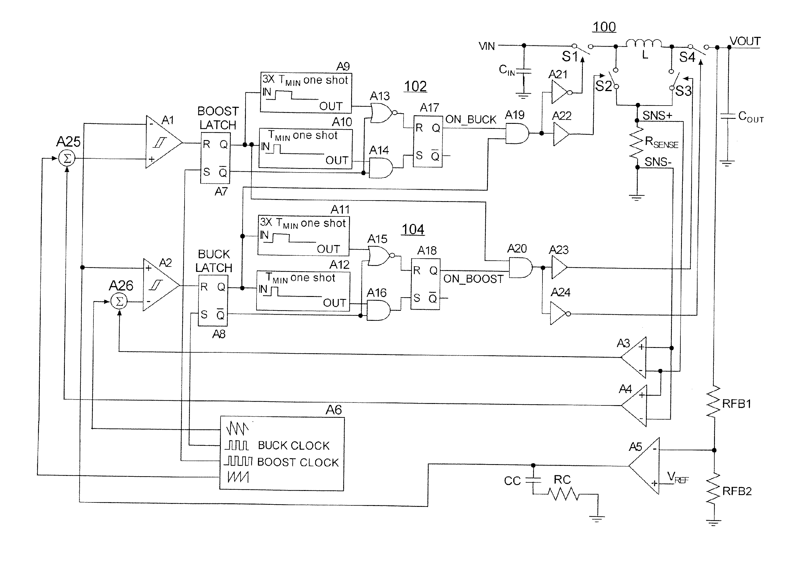
[0048]The present disclosure will be made with an examples of a switching regulator control arrangement shown in FIG. 6. It will become apparent, however, that the concepts described herein are applicable to any control scheme for controlling any power supply circuit for providing an output voltage or current above, below or equal to the input voltage or current.

[0049]As shown in FIG. 6, an exemplary step up-step down switching regulator 100 of the present disclosure includes inductor L and switches S1-S4 arranged to provide connection of the inductor L to input node VIN, output node VOUT and a ground node in boost, buck and buck-boost modes. When the input voltage VIN is well above the output voltage VOUT, the switches S1-S4 are controlled so as to set the regulator into a buck mode of operation. When the VIN is well below the VOUT, the switches S1-S4 are controlled so as to set the regulator into a boost mode of operation. When a difference between the VIN and the VOUT is within a...


PUM


Abstract

Novel circuitry and methodology for controlling a step up-step down switching regulator that produces a regulated output signal at an output node in response to an input signal at an input node, and has an inductive device, a plurality of switching circuits for providing connection of the inductive device to the input and output nodes and a ground node, and a switch control circuit for driving the switching devices so as to enable the power supply system to operate in a boost mode to increase the input signal, in a buck mode to decrease the input signal, and in a buck-boost mode when a difference between the input signal and the output signal is within a predetermined range. Buck-boost latch circuitry is provided for latching a transition between the buck mode and the buck-boost mode, or between the boost mode and the buck-boost mode based on a predetermined condition.

Description

[0001]This application claims priority of U.S. provisional application 61 / 325,690 filed on Apr. 19, 2010 and incorporated herewith by reference.TECHNICAL FIELD[0002]This disclosure relates to power supply systems, and more particularly, to controlling a step up-step down switching regulator using fixed frequency current mode control.BACKGROUND ART[0003]A step up-step down or a buck-boost switching regulator produces an output voltage VOUT that can be above, below, or at the same level as input voltage VIN. FIG. 1 shows a conventional step up-step down switching regulator including an inductor L, switches S1 and S2 coupled between the input VIN and the inductor L, and switches S3 and S4 coupled between the inductor L and the output VOUT. Input capacitor CIN and output capacitor COUT are respectively coupled to the input VIN and output VOUT. A sense resistor RSENSE is provided for sensing current. Current sense inputs SNS+ and SNS− arranged at both sides of the sense resistor RSENSE c...

Claims


Application Information

Patent Timeline
IPC IPC(8): G05F1/10
CPCH02M3/1582
Inventor REN, HONGCHEN, DANIEL LONGFALVEY, CHRISTOPHER THOMAS
Owner ANALOG DEVICES INT UNLTD
Why Eureka
Try Eureka