Combline filter

a filter and combline technology, applied in the field of combline filters, can solve the problems of large filter size, high cost, and inability to adjust, and achieve the effect of excellent suppression of sub-harmonic frequencies and low return loss

Active Publication Date: 2011-11-17
HITTITE MICROWAVE LLC
View PDF4 Cites 14 Cited by
  • Summary
  • Abstract
  • Description
  • Claims
  • Application Information

AI Technical Summary

Benefits of technology

[0007]This invention results from the realization that a microstrip combline bandpass filter having excellent suppression of sub-harmonic frequencies, a low return loss, and insertion loss having an amplitude equalization feature can be effected by a plurality of resonators each including a microstrip line, and a plurality of pairs of series coupled varactors, with a first end of each microstrip line coupled to one of the pairs of varactors, and a second end of each microstrip line coupled to ground.

Problems solved by technology

If the particular circuit of interest has an operating range that spans near an octave of frequencies, the required filter becomes complex and might need to be tunable.
These filters are large, expensive, limited in upper frequency range and their resonators would need additional tuning in order to match them to each other due to their inherent mismatch.
Also these filters have limited linearity performance.
The filters of the '630 patent, although promising low loss and high Q, are rather expensive, have repeatability challenges, require high operating control voltages and need high isolation on the control lines.

Method used


Image

  • Combline filter
  • Combline filter
  • Combline filter

Examples


Embodiment Construction

[0024]Aside from the preferred embodiment or embodiments disclosed below, this invention is capable of other embodiments and of being practiced or being carried out in various ways. Thus, it is to be understood that the invention is not limited in its application to the details of construction and the arrangements of components set forth in the following description or illustrated in the drawings. If only one embodiment is described herein, the invention is not to be limited to that embodiment.

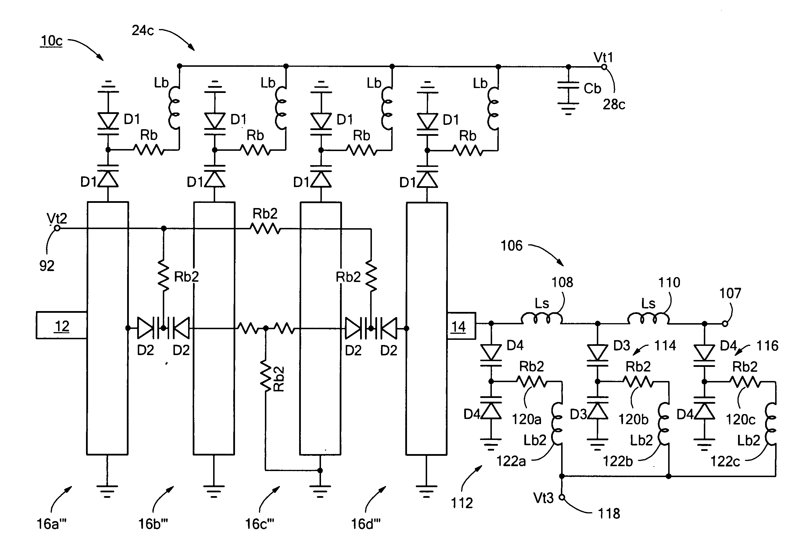
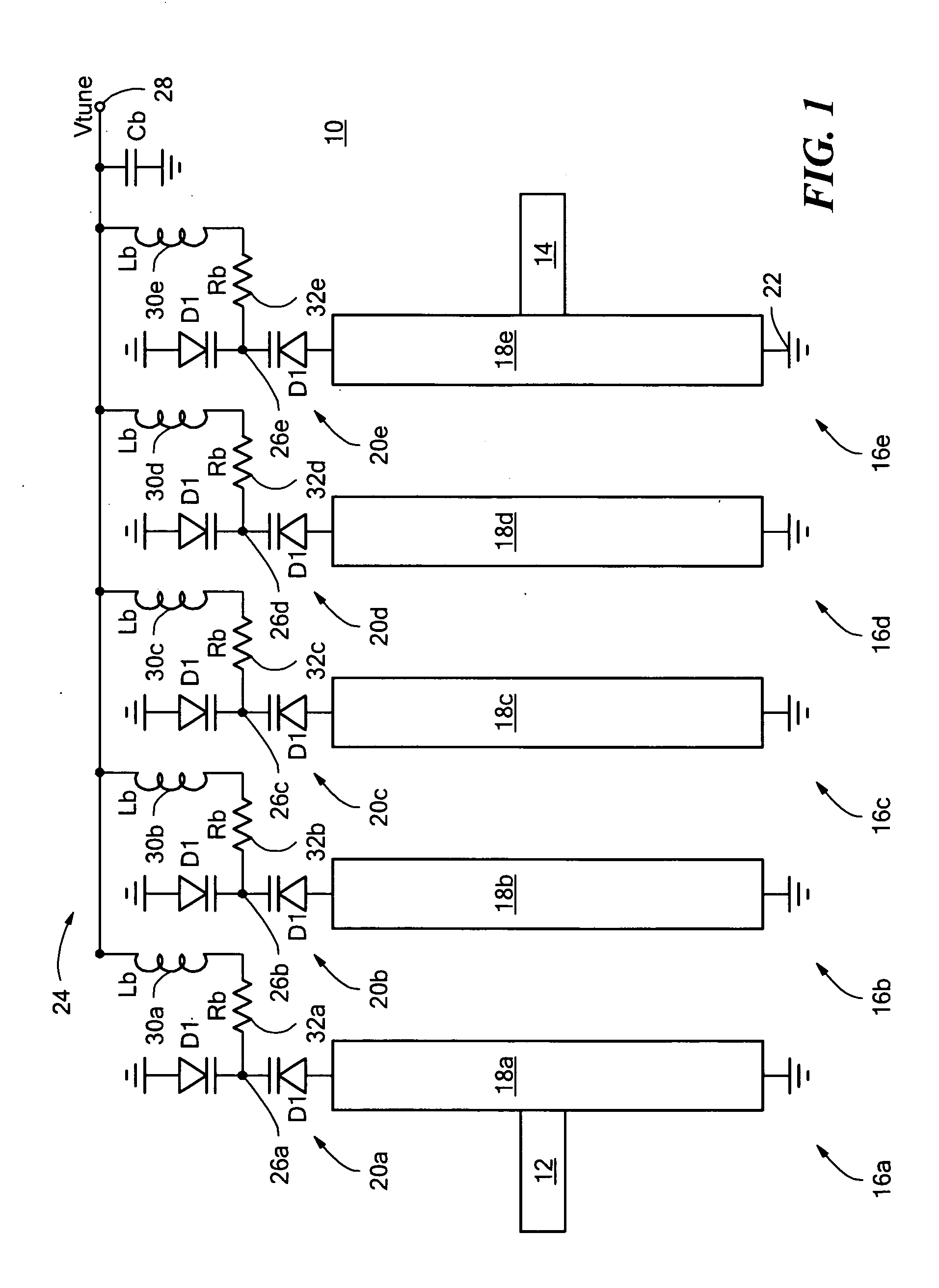
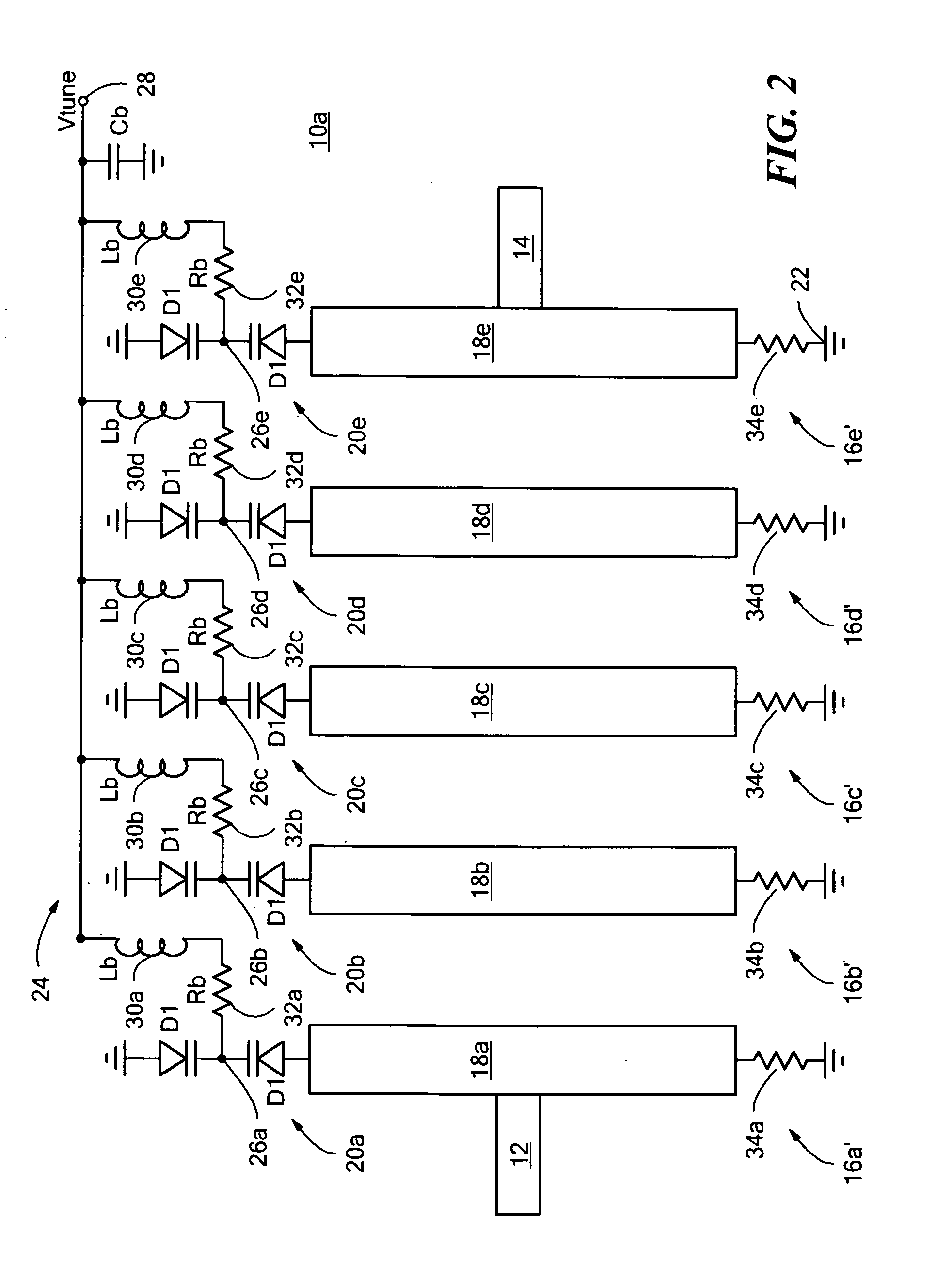
[0025]There is shown in FIG. 1 a preferred embodiment of a microstrip combline bandpass filter 10 in accordance with the subject invention. Combline bandpass filter 10 includes an input port 12, an output port 14, and a plurality of resonators 16a-e each including a microstrip line 18a-e. Resonator 16a is connected to input port 12, and resonator 16e is connected to output port 14. Combline bandpass filter 10 also includes a plurality of pairs of series coupled varactors 20a-e. A first end of ...


PUM


Abstract

A microstrip combline bandpass filter includes an input port, an output port, and a plurality of resonators each including a microstrip line having a first end and a second end. One of the plurality of resonators is connected to the input port, and another of the plurality of resonators is connected to the output port. The filter also includes a plurality of pairs of series coupled varactors. The first end of each microstrip line is coupled to one of the pairs of varactors, and the second end of each microstrip line is coupled to ground.

Description

RELATED APPLICATIONS[0001]This application hereby claims the benefit of and priority to U.S. Provisional Application Ser. No. 61 / 395,396, filed on May 12, 2010 under 35 U.S.C. §§119, 120, 363, 365, and 37 C.F.R. §1.55 and §1.78, which application is incorporated herein by reference.FIELD OF THE INVENTION[0002]The subject invention relates to a combline filter.BACKGROUND OF THE INVENTION[0003]Some electronic circuits, such as Frequency doublers and sub-harmonic VCOs, may generate unwanted frequency harmonics at half integers of the fundamental frequency. These spurious outputs are called sub-harmonics of the fundamental frequency. These unwanted signals are usually filtered with fixed mechanical or electrical circuits and brought down to acceptable levels. Such filtering preferably passes the fundamental frequency (Freq) with slight loss and good return loss while suppressing frequencies at Freq / 2 and 3*Freq / 2 and higher. If the particular circuit of interest has an operating range t...

Claims


Application Information

Patent Timeline
Patent Type & Authority Applications(United States)
IPC IPC(8): H03H11/04H03H7/00
CPCH01P1/212H01P1/20336H01P1/2039H01P7/082
Inventor ORAN, EKREM
Owner HITTITE MICROWAVE LLC
Why Eureka
Try Eureka