High Duty Cycle Radar with Near/Far Pulse Compression Interference Mitigation

Active Publication Date: 2011-11-17
MASSACHUSETTS INST OF TECH
View PDF8 Cites 85 Cited by
  • Summary
  • Abstract
  • Description
  • Claims
  • Application Information

AI Technical Summary

Benefits of technology

[0014]Compared to other radar signal processing techniques, embodiments of the present inventive techniques enable detection of targets that would otherwise be hidden or obscured by other targets or transmitted pulses. They also enable operation of radars at duty cycles close to or at the practical limit of 50%. At first glance, weighting weak return signals by disca

Problems solved by technology

If the pulse amplitude remains constant, however, then the total pulse energy drops as the pulse duration decreases, causing a corresponding decrease in radar range given a constant receiver sensitivity and noise floor.
Although increasing the pulse amplitude offsets the decrease in radar range due to the decrease in pulse duration, limits on peak pulse amplitude usually prevent simultaneous measurement of targets at the farther ranges with the finest possible range resolution.
Spreading the pulse energy in time also causes the return signal to spread in time, which may cause the peak of the return signal to fall below detectable limits despite the fact that the return signal contains a detectable amount of energy.
If the size difference between the targets is large enough, the sidelobes associated

Method used


Image

  • High Duty Cycle Radar with Near/Far Pulse Compression Interference Mitigation
  • High Duty Cycle Radar with Near/Far Pulse Compression Interference Mitigation
  • High Duty Cycle Radar with Near/Far Pulse Compression Interference Mitigation

Examples


Embodiment Construction

[0024]A description of example embodiments of the invention follows.

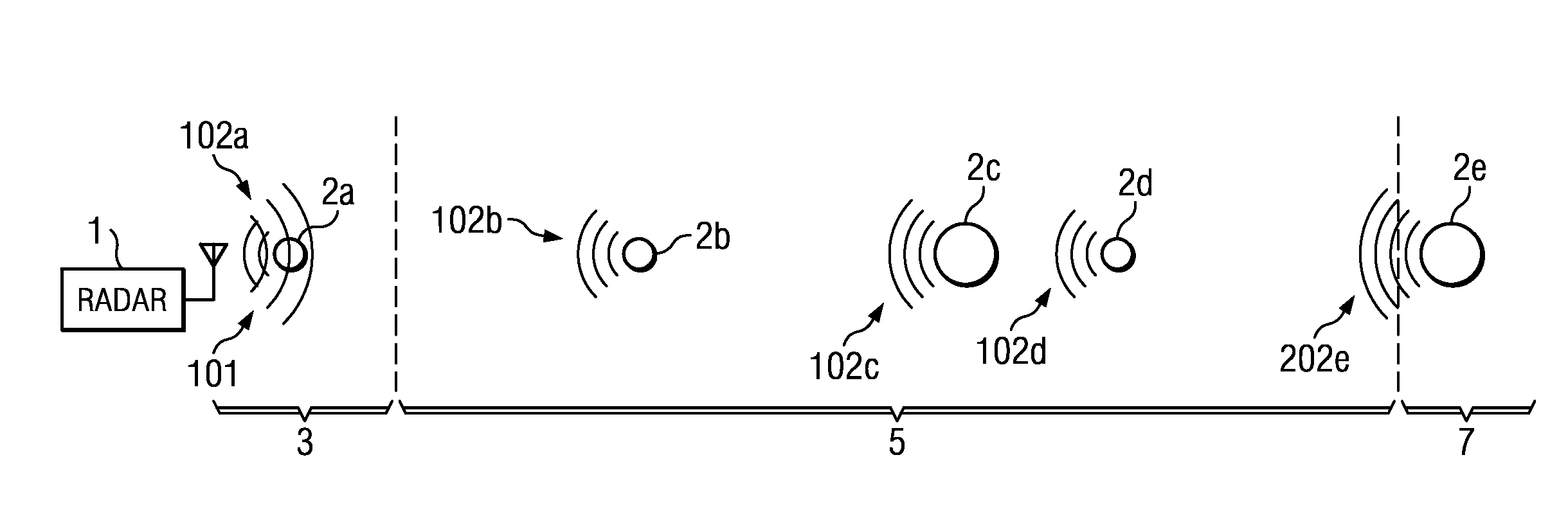
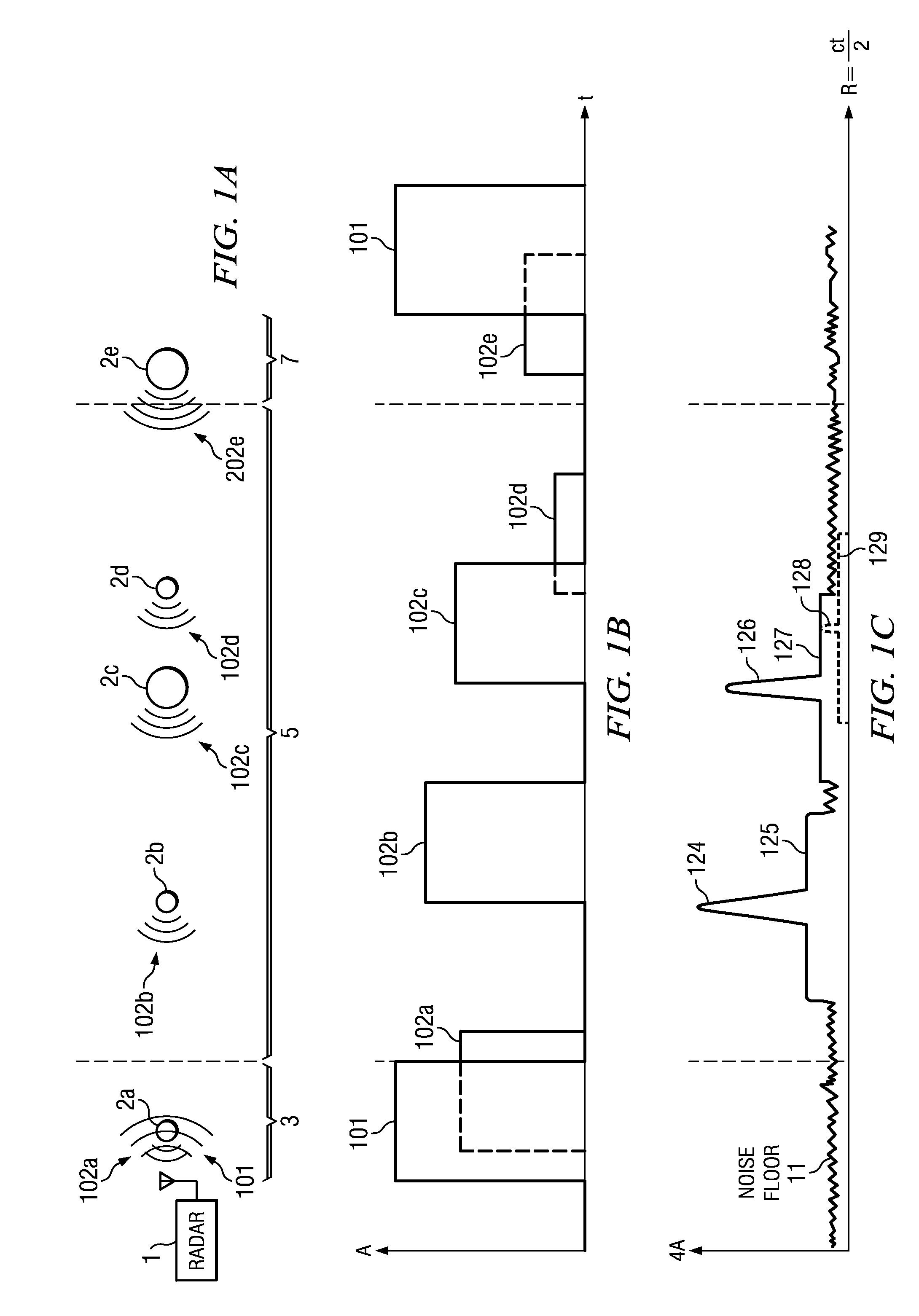
[0025]FIGS. 1A-1C illustrate conventional pulse compression processing for radar return signals from a variety of targets. As shown in FIGS. 1A and 1B, a radar 1 transmits signals 101 towards targets 2a-2e (collectively, targets 2) at a duty cycle of about 15%. The size of each target represents the size of its radar cross section. (The targets and ranges are not drawn to scale.) Each target reflects the transmitted pulse back towards the radar 1, which receives each reflected pulse at a delay equal to the product of the pulse propagation speed and the round-trip distance between the radar 1 and the subject target. In this example, target 2a reflects the transmitted signal 101 to produce a return signal 102a; target 2b produces a return signal 102b; and so on. The return signals are processed using standard pulse compression to produce the correlation peaks shown in FIG. 1C, where the location of each peak correspon...


PUM


Abstract

In conventional pulse compression processing, sidelobes from strong return signals may hide correlation peaks associated with weaker return signals. Example embodiments include methods of mitigating this near/far interference by weighting a received return signal or corresponding reference signal based the return signal's time of arrival, then performing pulse compression using the weighted signal to produce a correlation peak that is not hidden by sidelobes from another return. Multi-frequency processing can also be used to reduce the pulse width of the transmitted pulses and received return signals, thereby mitigating near/far interference by decreasing the overlap between signals from nearby targets. Weighting can be combined with multi-frequency pulse transmission and reception to further enhance the fidelity of the processed correlation peak. Weighting and multi-frequency processing also enable higher duty cycles than are possible with conventional pulse compression radars.

Description

GOVERNMENT SUPPORT[0001]This invention was supported, in whole or in part, by contract no. FA8721-05-C-0002 from the Department of the Air Force. The Government has certain rights in this invention.BACKGROUND OF THE INVENTION[0002]Radar, sonar, lidar, and other remote sensing techniques involve locating a target by measuring the time-of-flight of an electromagnetic pulse from an antenna to the target and back again. The farther the target is from the antenna, the longer the delay between transmission of the pulse and reception of the return signal from the target. The delay increases linearly with the range to the target, but the amplitude of the return signal varies as 1 / R4, where R is the range to the target. Thus, a doubling of radar range requires a sixteen-fold increase in amplitude of the emitted pulses.[0003]To achieve fine range resolution, the emitted pulses should have wide bandwidth. For single-frequency pulses, the bandwidth increases as the pulse width decreases, so mak...

Claims


Application Information

Patent Timeline
IPC IPC(8): G01S13/28G01S13/08
CPCG01S7/023G01S13/282G01S7/292G01S7/0232
Inventor SONG, WILLIAM S.
Owner MASSACHUSETTS INST OF TECH
Why Eureka
Try Eureka