
System, method, program, and integrated circuit for hearing aid

a hearing aid and integrated circuit technology, applied in the field of hearing aid systems, can solve the problems of difficult to perceive the subsequent sound, difficult to perceive the close frequency sound, and difficult to perceive the soft sound as compared to a normal person, and achieve the effect of improving the clarity of speech

Active Publication Date: 2011-11-17
PANASONIC CORP
View PDF0 Cites 25 Cited by
  • Summary
  • Abstract
  • Description
  • Claims
  • Application Information

AI Technical Summary

Benefits of technology

"The present invention relates to a hearing aid system that includes two hearing aid devices to improve hearing. The system uses a frequency spectrum of speech to identify and distinguish between vowels and consonants. The system also takes into account the impact of masking on speech perception and proposes a dichotic-listening binaural hearing aid processing to improve frequency resolution and temporal resolution. The technical effect of the invention is to improve the clarity and ease of speech recognition for people with hearing loss."

Problems solved by technology

The frequency masking occurs when a large sound with a specific frequency component masks a sound with a frequency which is close to the specific frequency component and thus makes it difficult to perceive the sound at the close frequency.
The temporal masking occurs when a preceding sound masks a subsequent sound and thus makes it difficult to perceive the subsequent sound.
Due to a decrease in hearing, it is harder to perceive a soft sound as compared to a person with normal hearing.
Thus, a person with hearing loss is likely to misidentify a vowel.
Thus, it is harder for a person with hearing loss to perceive a subsequent consonant.

Method used


Image

  • System, method, program, and integrated circuit for hearing aid
  • System, method, program, and integrated circuit for hearing aid
  • System, method, program, and integrated circuit for hearing aid

Examples


embodiment 1

[0094]FIG. 8 is a diagram showing an external view of the hearing aid system in the first embodiment according to the present invention.

[0095]A hearing aid system 1000a includes: first and second hearing aid devices 100 and 110 which are to be fitted on the left and right ears, respectively; and a remote control 120. It should be noted that the hearing aid system 1000a corresponds to the hearing aid system 1000 shown in FIG. 7, and that the first and second hearing aid devices 100 and 110 correspond to the first and second hearing aid devices 1100 and 1200, respectively, shown in FIG. 7.

[0096]The first hearing aid device 100 is fitted on, for example, the left ear, and includes: a main unit which performs amplification to compensate hearing loss; a sound pickup unit 101 included in the main unit; an output unit 106; and a switch 109. The second hearing aid device 110 has the same configuration as the first hearing aid device 100, and is fitted on, for example, the right ear. More sp...

first modification

(First Modification)

[0160]Here, the first modification in the present embodiment is described. As compared to the first and second hearing aid devices 100 and 110 of the hearing aid system 1000a in the stated embodiment, the arrangement of hearing compensation units is different in first and second hearing aid devices of a hearing aid system in the present modification.

[0161]FIG. 17 is a functional block diagram of the hearing aid system in the present modification.

[0162]A hearing aid system 1000b in the present modification includes: first and second hearing aid devices 100a and 110b; and a remote control 120.

[0163]The first and second hearing aid devices 100a and 110b in the present modification include the same components as the first and second hearing aid devices 100 and 110 in the above embodiment, respectively. However, the hearing compensation units 105 and 115 are arranged before the division units 102 and 112, respectively. To be more specific, each of the hearing compensa...

second modification

(Second Modification)

[0165]Here, the second modification in the present embodiment is described. As compared to the hearing aid system 1000a in the above embodiment, a division unit has a different configuration in a hearing aid system of the present modification.

[0166]FIG. 18 is a diagram showing a configuration and connection relation of the division unit included in the hearing system in the present modification.

[0167]As shown in FIG. 18, a division unit 102a in the present modification includes an all-pass filter (APF) 901, a BPF 902, and a subtraction unit 903. The APF 901 receives an acoustic signal outputted from the sound pickup unit 101, and outputs signals in all frequency bands (i.e., signal in an entire band) included in the acoustic signal. The BPF 902 is a filter for extracting a signal including main speech components (i.e., the signal in the voice band), and has the same characteristics as the BPF 202 shown in FIG. 10 in the stated embodiment. More specifically, the ...


PUM


Abstract

To provide a hearing aid system (1000) performing dichotic-listening binaural hearing aid processing which improves the clarity of speech and maintains the spatial perception ability. Each of first and second hearing aid devices (1100, 1200) includes a sound pickup unit (1110, 1210) and an output unit (1120, 1220) outputting a sound indicated by a suppressed acoustic signal. The hearing aid system (1000) includes: a first band suppression unit (1300) generating the suppressed acoustic signal indicating the sound outputted from the output unit (1120), by suppressing a signal in a first suppression-target band out of the acoustic signal outputted from the sound pickup unit (1110); and a second band suppression unit (1400) generating the suppressed acoustic signal indicating the sound outputted from the output unit (1220), by suppressing a signal in a second suppression-target band out of the acoustic signal outputted from the sound pickup unit (1210). The suppressed acoustic signals indicating the sounds outputted respectively from the output units (1120, 1220) include, in common, a signal in a non-voice band included in the acoustic signal.

Description

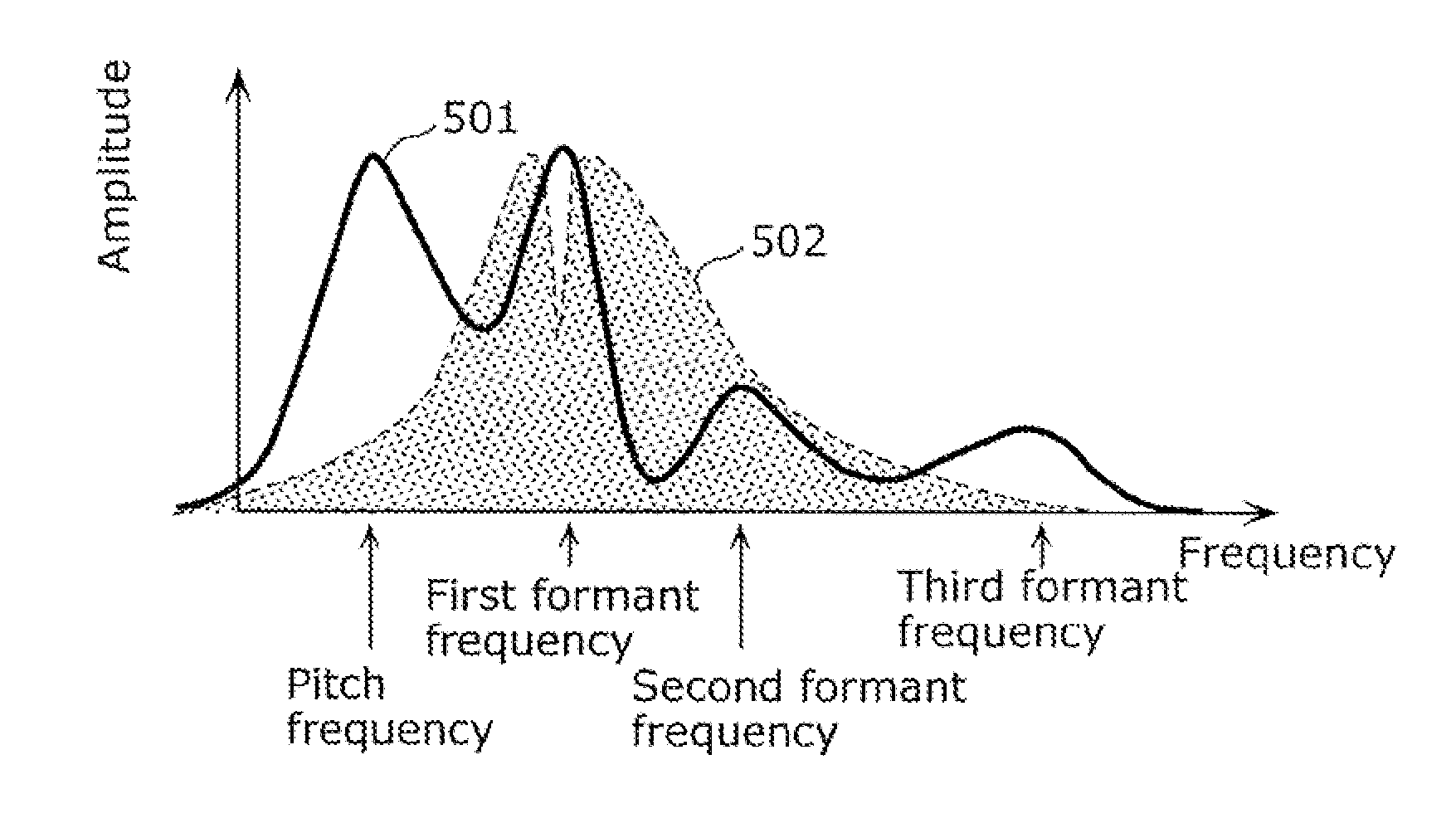
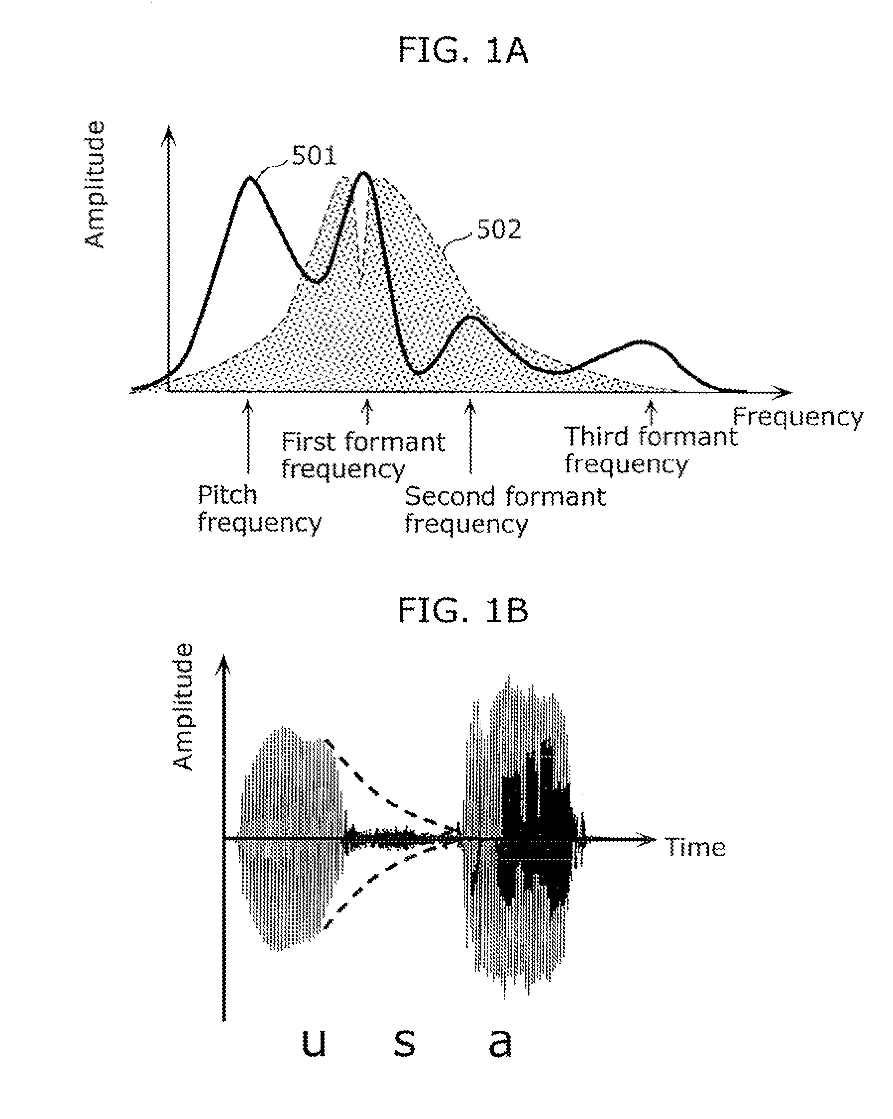
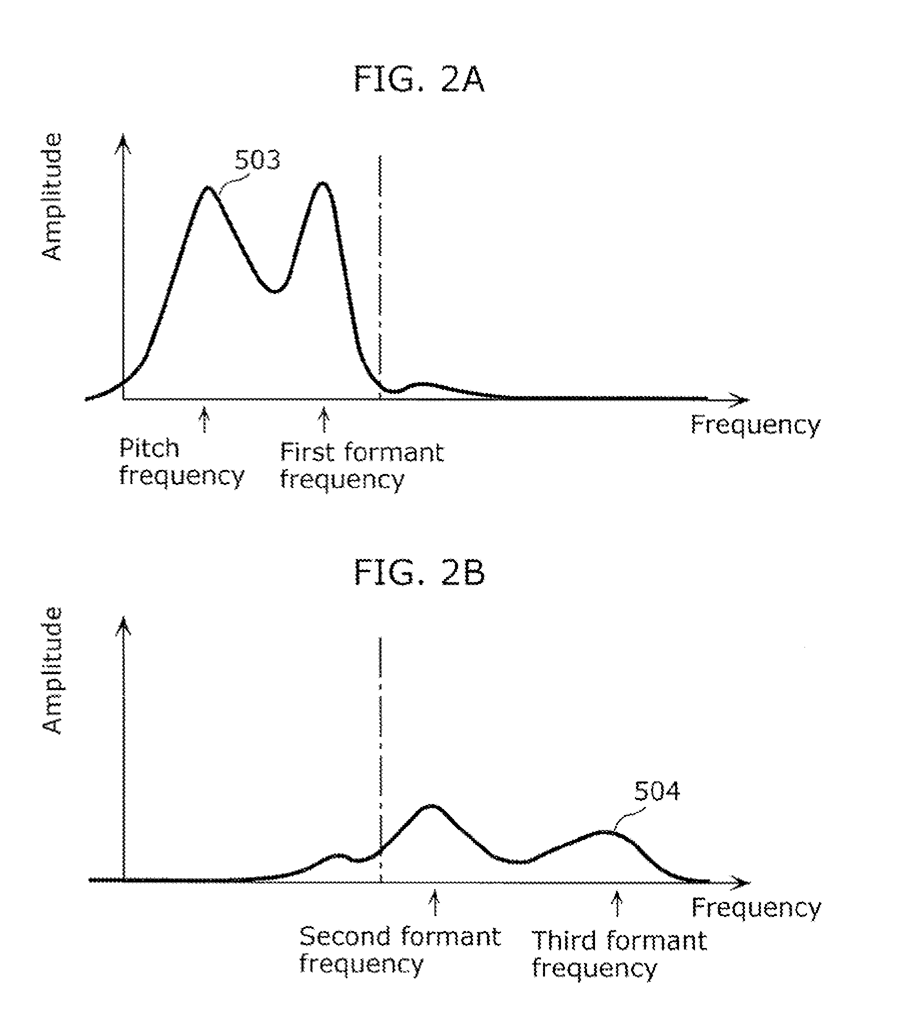
TECHNICAL FIELD[0001]The present invention relates to a hearing aid system including two hearing aid devices to aid in hearing.BACKGROUND ART[0002]Firstly, acoustic characteristics of speech are described.[0003]FIG. 1A shows a diagram showing a frequency spectrum of speech. In FIG. 1A, the horizontal axis represents frequency and the vertical axis represents amplitude. A solid line 501 in FIG. 1A shows an example of speech represented by a frequency spectrum. A speech frequency spectrum has several peaks on the frequency axis. The peak of the lowest frequency indicates a fundamental speech frequency called a pitch, and is different depending on the tone of voice. In general, the peak of the lowest frequency is between 125 Hz and 300 Hz. Voice is a result of resonance (vibration) of a sound wave generated by vocal cord vibration, in the vocal tract which is a path from the pharynx to the lips. The resonance frequency is called a formant. The formant with the lowest frequency is calle...

Claims


Application Information

Patent Timeline
Patent Type & Authority Applications(United States)
IPC IPC(8): H04R25/00G10L21/0332
CPCG10L21/02H04S2420/07H04R25/552H04R25/50
Inventor TAKAGI, YOSHIAKIITO, GEMPONOGUCHI, EIJIKATAYAMA, TAKASHI
Owner PANASONIC CORP
Learn More